SUMMARY AND CONCLUSIONS FROM THIN AIRFOIL THEORY
Up to this point, in order to be able to solve practical problems, the fluid dynamic equations were considerably simplified and even the boundary conditions were approximated. However, in spite of these simplifications, some very important results were obtained in this chapter:
1. The lift slope of a two-dimensional airfoil is 2л as shown by Eq. (5.66).
2. The pitching moment at the aerodynamic center (at cl4) is independent of angle of attack (excluding airfoil’s stalled conditions).
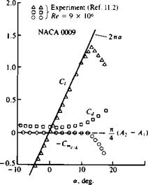
These two very important results are very close to experimental data in the low angle of attack range, as shown in Fig. 5.19. When the angle of attack
FIGURE 5.19
 Lift and pitching moment of a NACA 0009 airfoil.
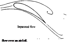
increases beyond the limits of the small angle of attack assumption, the streamlines do not follow the airfoil surface shape (Fig. 5.20) and the flow is considered to be separated. This results in loss of lift, as indicated by the experimental data in Fig. 5.19 (for a> 10°) and this condition is called airfoil stall.
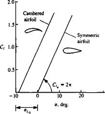
3. Airfoil camber does not change the lift slope and can be viewed as an additional angle of attack effect (au in Eq. (5.66)). This is shown schematically by Fig. 5.21. The symmetric airfoil will have zero lift at ar = 0 while the airfoil with camber has an “effective” angle of attack that is larger
by <*u-
4.
 |
The trailing edge section has a larger effect on the above camber effect. Therefore, if the airfoil lift needs to be changed without changing its angle
FIGURE 5.21.
 Schematic description of airfoil camber effect on the lift coefficient.
of attack, then changing the chordline geometry (e. g., by flaps, or slats) at the trailing edge region is more effective than at the leading edge region.
5. The effect of thickness on the airfoil lift is not treated in a satisfactory manner by the small-disturbance approach, but will be calculated more accurately in the following two chapters.
6. The two-dimensional drag coefficient obtained by this model is zero and there is no drag associated with the generation of two-dimensional lift. Experimental airfoil data, however, includes drag due to the viscous boundary layer on the airfoil, which should be included in engineering calculations. The experimental drag coefficient values for the NACA 0009 airfoil are also plotted in Fig. 5.19 and for example the “zero-lift” drag coefficient is close to Cd = 0.0055.


