THE AERODYNAMIC LOADS
Solution of the aforementioned problems (e. g., the thickness or lifting problems) results in the velocity field. In order to obtain the aerodynamic loads the pressures need to be resolved by using the Bernoulli equation (Eq.
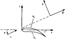
(4.4) ). Also, the aerodynamic coefficients can be derived either in the wing or in the flow coordinate system. In this case of small disturbance flow over wings, traditionally, the wing coordinates are selected as shown in Fig. 4.10. The velocity at any point in the field is then a combination of the free-stream velocity and the perturbation velocity
q=^<2oocosar + —, —, — – fQooSina’j (4.51)
![]()
 FIGURE 4.10
Wing-attached coordinate system.
Substituting q into the Bernoulli equation (Eq. (4.4)) and taking into account the small-disturbance assumptions (Eqs. (4.13) and (4.14), and a« 1) yields
p»-p = ^0?2-G«)
![]()
— 0» cos2 a + 2Qn cos a— + 2 L dx
The pressure coefficient Cp can be defined as
Note that at a stagnation point q = 0 and Cp = 1. In the undisturbed flow q = Q„ and Cp = 0. The aerodynamic loads, then, can be calculated by integrating the pressures over the wing surface:
F= — I pndS (4.54)
■’wing
When the surface shape is given as in Eq. (4.6) then the normal to the surface is given by Eq. (4.7), which with the small-disturbance approximation
becomes:
J_ (_dV _ /_dq _3q A
|VF| dx ’ dy ’ / дх’ ду/
Consequently the components of the force F can be defined as axial, side, and normal force
|
p f / driu дур x LJPu Эх Pl Эх/ |
| dx dy |
(4.55) |
|
f ( Эг)и dr) A |
1 dx dy |
(4.56) |
|
F2= I (p,-pu)dxdy ■’wing |
(4.57) |
Here the subscripts и and / represent the upper and lower wing surfaces, respectively. Aerodynamicists frequently refer to the forces in the free-stream coordinates (Fig. 4.10), and therefore these forces must be transformed accordingly. For the small-disturbance case the angle of attack is small and therefore the lift and drag forces are
D = Fx cos a + Fz sin a L = —Fx sin a + Fz cos a ~ Fz
Note that the evaluation of drag by integrating the pressure distribution is considered to be less accurate than the above formulation for the lift.
In the case when the wing is assumed to be thin, the pressure difference across the wing Ap is evaluated (positive Ap is in the +z direction) as
ЭФ г ЭФ ]
Ар = Pt ~ Ри = Р» – PG-(*> У> 0-) – [p. о – pG~ (X, y, 0+) J
г яф дф и
= рЯ~[-^(х, У>в+)–^(Х’У,0-) (4-58)
If the singularity distribution is assumed to be placed on the x—y plane then the pressure difference becomes:
Source distribution. Because of symmetry,
ЭФ ЭФ
and
ГЭФ ЭФ 1
Ap = pG»[— (*> У> 0+) _ у (x> У> °+)J = 0 (4.59a)
![]()
Doublet distribution. In this case
and the pressure difference becomes
![]() Ap = pG~ ^ АФ(дс, у) = – pQo*
Ap = pG~ ^ АФ(дс, у) = – pQo*
where АФ = Фи — Ф/.
Vortex distribution. For the vortex distribution on the x-y plane the pressure jump can be modeled with a vortex distribution yy{x, y) which points in the у direction , such that
— (x, y, 0±) = ± 2Yy(x, y)
therefore, the pressure difference becomes
Ap = pG« АФ(дг, у) = pQ„Yy(x, у) (4.59c)
The aerodynamic moment can be derived in a similar manner and as an example the pitching moment about the у axis for a wing placed at the z = 0
plane is
Mx=o=J Apxdxdy (4.60)
•’wing
Usually, the aerodynamic loads are presented in a nondimensional form. In the case of the force coefficients where F is either lift, drag, or side force the the corresponding coefficients will have the form
![]() F
F
ipQls
where 5 is a reference area (wing planform area for wings). Similarly the nondimensional moment coefficient becomes
Here, again M can be a moment about any arbitrary axis and b is a reference moment arm (e. g., wing span).


