THE LUMPED-VORTEX ELEMENT
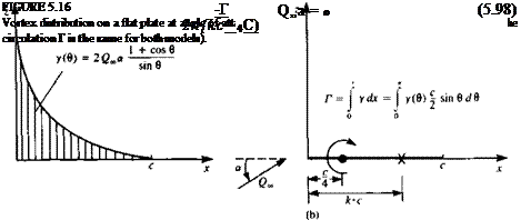
Based on the results obtained for the lifting symmetrical airfoil (flat plate), it is possible to develop a simple “lifting element.” The vortex distribution on such a flat plate airfoil can be obtained from Eq. (5.48) as
y(e)-=2Q00a]-r^0^- (5.97)
sin a
which is shown schematically in Fig. 5.16a. From a far field point of view, this can be replaced by a single vortex with the same strength Г = y(x) dx.
Since the lift of the symmetric airfoil
L = PQS
acts at the center of pressure (at the quarter-chord for the flat plate), the concentrated vortex is placed there.
If the lifting flat plate is to be represented by only one vortex Г, then the boundary condition requiring zero normal flow at the surface can be specified
 |
at only one point too. Assuming that this point is at a distance к • c along the x axis (Fig. 5.166) then the boundary condition of zero normal velocity can be specified as
In order for this model to simulate the results of the thin airfoil the corresponding value of the circulation for a flat plate (Eq. (5.72)) is substituted:
Г = ncQ^a
![]() -jrcQ^a 2л(кс — |c)
-jrcQ^a 2л(кс — |c)
The solution of this equation provides the point at which the boundary condition needs to be specified, which is called the collocation point:
к = (5.99)
Note that this representation is based on results that account for the Kutta condition at the trailing edge. This is the main reason for some of the good approximations that can be obtained when using this model. Some of the advantages of using this lifting element for the estimation of some aerodynamic effects are shown in the following examples.
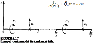
Example 1: Tandem airfoils. The useful application of this simple model can be demonstrated by investigating the lift of the two-airfoil system, shown in Fig. 5.17. The circulations of the two airfoils are represented by Г, and Г2, and the
 |
|
two boundary conditions at the two collocation points, which require that the normal velocity component will be zero, are w, = tv2 = 0. The normal velocity component at each collocation point consists of the influence of the two vortices and the free stream normal component and when specified at these points the two boundary conditions are:
![]()
![]() —г —r2
—г —r2
—— 1—– =—t-
2л2с 2л(с/2)
The solution of this system is
![]() Г, = I iicQ^a Г2 = І лсО„а
Г, = I iicQ^a Г2 = І лсО„а
Thus, clearly, the front airfoil has a larger lift due to the upwash induced by the second airfoil, and because of the same but reversed interaction the second airfoil will have less lift. Also, this effect is stronger when the airfoils are closer and the interaction will disappear as the distance increases. The importance of this result is that the immediate effects of the tandem airfoil configuration could be estimated with minimum effort.
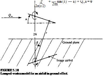
Example 2: Ground effect. Another simple example is the airfoil near the ground, which is modeled by using the mirror-image method (Fig. 5.18). In order to create a straight streamline at the ground plane, two symmetrically positioned airfoils are considered. Again, using the lumped vortex element, the normal velocity component at the collocation point due to the bound vortex is —Г/2л(с/2). The influence of the image vortex, which has the same strength but in the opposite direction and is located at a distance 2h under the primary vortex, is then
Here r = V4h2 + c2/4 is the distance from the image vortex to the collocation point, and sin f} = (c/2)/r. Requiring that the sum of the contributions to the
 |
|
normal velocity component at the collocation point is zero yields
Assuming a is small compared to |8 (equivalent to assuming that the circulation is linear in a) results in
4h2 + c2I4 г с2 l
T(h) = T(h=cc) – ^ =Г(Ь=сф+— j (5.103)
Here Г(Л) is the value of circulation with ground proximity and this result clearly indicates that the circulation (and lift) will be increased by the proximity of the ground.


