Viscous/Inviscid Interaction Procedures Based on Displacement Thickness Concept
Consider steady 2-D flows. For high Reynolds numbers, an inviscid model can be used everywhere except in a thin viscous layer over the body and in its wake. The latter is needed since the inviscid flow theory allows a slip velocity at the solid surface and the physical “no slip” boundary condition can not be imposed, in general.
If the thin viscous layer is not introduced, the inviscid flow profile, extended to the wall, will have more mass flow rate than the corresponding viscous flow profile as shown in the figure, see Fig. 9.3.
© Springer Science+Business Media Dordrecht 2015
J. J. Chattot and M. M. Hafez, Theoretical and Applied Aerodynamics,
DOI 10.1007/978-94-017-9825-9_9
|
|
|
It is assumed that the viscous stress contributions are negligible outside the thin layer of thickness S, compared to the pressure and inertia forces.
As discussed before in the previous chapter on boundary layers, Prandtl introduced the concept of displacement thickness, where the body is displaced such that the inviscid flow profile over the displaced body will have the same mass flow rate as the viscous flow profile over the original body. The equation for such a displacement thickness S*, is given by
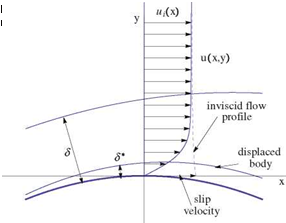 |
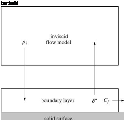
Fig. 9.4 Viscous/inviscid interaction
For incompressible flows, p = pi = const. Notice also, both 6 and 6* are changing from one station to another, in general. However, for a self-similar solution of boundary layer over a flat plate without pressure gradient, u/ui is a function of П = y/S only, hence the ratio 6*/6 becomes a constant. In the non similar case, ui changes in the streamwise direction as well.
Now the viscous/inviscid interaction can be described by the following diagram. See Fig. 9.4.
The boundary layer and inviscid flow calculations are coupled. Boundary layer codes require the inviscid surface pressure distributions from the inviscid flow codes,
while the inviscid flow calculations are performed over the displaced body (and wake). In general, the two calculations must be performed simultaneously.
For some cases, mainly attached flows, the interaction is weak, and the two calculations are decoupled and the final results are obtained via iterations. To start the procedure, 6*(x) is assumed known (for example through ignoring the pressure gradient) and the cycle is started until convergence. This is not always the case. A limit cycle may occur and hence the results are not satisfactory. The convergence problems are critical for the viscous effects to be properly accounted for.
The feedback of the boundary layer to the inviscid flow can be imposed through a transpiration boundary condition to avoid changing the grid in the inviscid flow calculations from iteration to iteration. Using small disturbance formulation, the same grid is used for all iterations. Instead of imposing the no penetration boundary condition on the displaced body (i. e. the inviscid flow is tangent to the displaced body), an equivalent condition on the original body is derived using the Taylor series expansion as follows.
Integrating across the boundary layer and using the Leibnitz rule, one gets in terms of local coordinates (x, y):
|
dpu Sdpv d У + d У = 0 dx 0 dy |
(9.2) |
|
dS |
|
|
pu dy – pi u – + pi v – = 0 d x |
(9.3) |
|
d dx |
|
S |
|
0 |
|
s |
|
0 |
The definition of displacement thickness can be written
s
![]() pu dy = piui (S – S*)
pu dy = piui (S – S*)
0
after substitution, the equation now reads

![]() dx dx
dx dx
A Taylor expansion of (pV) provides the transpiration mass flux to first order as
(pv)0 = (pv)i – S i – + O (S2) = pi Vi + S – – + O (S2) ~ (piui S*)
dy dx dx
(9.6)
Hence, if a flux (pv)0 is blown at the original surface given by the above equation, the inviscid flow will be tangent to the displaced body.
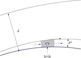 |
The above statement is a consequence of conservation of mass for the inviscid flow applied to the control volume shown in Fig. 9.5. In the above argument, the variation of ptut across the boundary layer is ignored.
In the following, four formulations are considered:
(1) Coupling integral formulations of both inviscid and viscous flow regions.
(2) Coupling the numerical solution of the partial differential equations of the inviscid flow with integral equations of boundary layers.
(3) Coupling the numerical solution of the partial differential equations of the viscous flow with the integral equations of the outer inviscid flows.
(4) Coupling numerical solutions of partial differential equations of both the inviscid and viscous flow regions.
After these four formulations are covered, other approaches based on domain decomposition will be addressed in latter part of this chapter.


