CHARACTERISTICS OF SPOILERS
Definition. A spoiler is basically a device that “spoils” the flow about a wing section (or possibly about a tail – surface) in such a manner that a lift differential is produced. Under certain conditions (when placed at the pressure side) such devices also produce lift, however, and their characteristics then resemble those of ordinary aileron flaps. The distinction between the two types of control thus seems to depend upon the fact whether or not spoiling of the flow pattern is an intended and primary or necessary effect of the device (12).
Mechanism. It is explained in Chapter II how circulation around an airfoil is reduced by friction and boundary – layer displacement. When enlarging the B’layer thickness at the suction side or when replacing that layer by a “wake” behind some obstruction such as a spoiler, lift is further reduced. It follows from this mechanism:
a) that spoilers can most efficiently be applied at the suction (upper) side
b) that effectiveness is highest when placing the spoiler at or near the point of maximum local velocity or minimum pressure
c) that the spoiler effectiveness increases with the lift coefficient.
The effectiveness increases approximately in proportion to the height of the spoiler flap. The lift differential produced in thin (t/c := 4 or 6%) and straight foil sections is in the order of
– ACL =(3 or 4) h/c (20)
It may thus seem to be possible to use a spoiler, for example, in a horizontal tail surface, and they have indeed been used (or proposed to be used) in the control surfaces of missiles (possibly for reasons other than aerodynamic). We will see, however, that spoilers can be used more profitably in combination with round-nosed (15) and cambered foil sections that exhibit trailing edge stalling as in wings, and they are then used for lateral control.
|
103 |


 As a consequence, the spoiler can be the most effective means of lateral airplane control at higher lift coefficients (i. e. at low flying speeds) where conventional ailerons have the tendency to fail (a) because of separation from their suction side, (b) because of rolling moment (in foot-pounds) being proportional to V2, where V = speed of the airplane.
Thin Foil Sections. As explained in Chapters II and IV there are two basic types of foil sections:
a) essentially straight and thin sections with leading-edge stalling
b) round-nose and more or less cambered sections with trailing-edge stalling.
Figure 16 presents the lift effectiveness of a “spoiler” flap (simulated by a triangular ridge) extended from the upper side of a thin and straight foil section. The lift differential produced is:
a) comparatively small
b) nearly independent of the angle of attack
c) comparatively independent of location along chord.
|
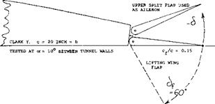
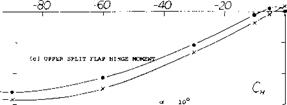
Figure 15. Double split flap arrangement, combining a lifting flap with an upper-side lateral control flap, tested (7,k) between tunnel walls. |
(15) Spoilers used in thin and straight foil sections:
(a) Hammond, On 4 and 6% Foils, NACA RM L56F20.
(b) Groom, Pressure Distributions, NACA RM L58B05.
Solid Spoiler Flaps. The simplest design of a spoiler is a split-type flap, deflected from the upper side of a wing. Solid flaps of this kind have several shortcomings, however:
a) their influence upon lift as a function of deflection, develops in a continuous manner.
b) they are likely to cause vibration and buffeting.
c) they have hinge moments of appreciable, if not considerable, magnitude.
d) their effectiveness is subjected to a timewise delay between their deflection and the reduction of the lift.
For practical purposes all of these shortcomings can be eliminated by using non-solid spoilers (such as grids, or preferably rake-like devices) and by extending them in the direction normal to the upper surface, from within, usually along a certain arc, provided by a lever suitably hinged to the wing structure. An example of a realistic, if experimental, full-scale installation of this type is illustrated in figure 22,c.
|
A = 4 X = c/2 c =2.5 INCH Figure 16. Example of a spoiler flap on the upper side of a thin and straight foil section tested (15) on a rectangular wing having an aspect ratio of 4. |
Time Lag is very important if undesirable characteristic of spoilers. The change of circulation through trailing-edge displacement by means of a flap takes place without any noticeable (although yet measurable) time lag between deflection and the result in form of a lift differential. The change in flow pattern after projecting a spoiler, however, can take so much time that the reaction of the airplane is delayed objectionably. As an example, the tunnel-tested history of two particular spoilers is presented in figure 17. Fluid-dynamic time (z) is conveniently measured by the number of chord lengths traveled. That number is the non-dimensional ratio
X/c = z V/c (21)
where X = z V = distance traveled within the time z. In the case of the solid spoiler flap in figure 17,a, sudden projection (which takes X/c = 1.5 as indicated by a first arrow) even causes the lift at first to increase slightly. The flow does not separate immediately. Rather, it climbs over the obstacle which thus exhibits a camber effect remotely similar to that expected in non-viscous fluid flow. It then takes 4 chord lengths before the lift starts dropping below the original undisturbed level, and some 12 lengths before it finally reaches the terminal lower level. The airplane response time to a lateral control force will be added to the time lag of the spoiler, thus causing a considerable delay to the desired control correction. Such a delay will also be an irritation to the pilot through the lack of tightness in the control system. As a consequence, the danger of overcontrolling is very great by too much control-stick or – wheel deflection after the original deflection did not produce any
Rake-Type Spoiler. Measured time-lag data from a number of sources have been assembled in figure 18. Conventional ailerons are included for comparison. It is seen that the delays A and B, as defined in the tabulation, are roughly as follows:
in conventional ailerons A = О В = 5
for solid spoiler plates A = 7 В = 20
for rake-type spoilers A = 2 В = 7
The improvement due to ventilation of the space behind the spoiler, as in the rake-type, is very considerable.
|
TYPE OF SPOILER A В z (sec)
A and В indicate chord lengths traveled, before lift reduction begins (A) and before the terminal reduced level of lift is reached (B). The time "2,11 represents the delay corresponding to A, under assumed landing conditions where V л 140 ft/sec (^80 kts) and for c A*7 ft; hence "z" = (7/140) A = A/20. |
![]()

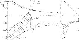
The pressure distribution around a foil section (in the center of a low-aspect-ratio rectangular wing model) is presented in figure 19 without, and in the presence of, a rake-type spoiler at the location as shown. The lift differential produced (ACl = —0.5) corresponds primarily to a reduction of the negative amount (suction) of the pressure coefficient at the suction side, ahead of the spoiler, in the order of ACp = 1. In the presence of the spoiler, circulation is evidently appreciably reduced. A considerably enlarged boundary layer springs from the spoiler. Disregarding the trailing-edge flap (to be discussed later), the suction-side flow is not separated, however.
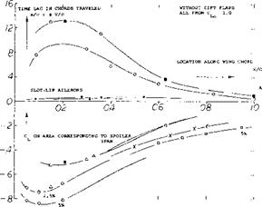
Chordwise Location. Figure 20 presents effectiveness as well as time lag of spoilers as a function of their chordwise location. As mentioned before, effectiveness (measured in the form of lift reduction ACL from CL0 = 1, produced by full spoiler extension) increases as the spoiling device is moved forward along the foil chord. Maximum effect is obtained between X/c = 0.2 and 0.3, and that effect can be appreciably higher than that of an aileron at the trailing edge. The time lag (as in the upper part of figure 20) also increases as the spoiler is moved forward. Time lag can be said to be approximately proportional to effectiveness. Disregarding a lesser influence of the magnitude of the original lift coefficient (at which the spoiler is used), the total delays as listed in figure 18 and as tested elsewhere, may be approximated by
X/c = к ACL (22)
where к = (x/c)/ACl has roughly values as follows:
к = 24 for solid-plate spoilers
= 8 for rake-type spoilers
= 6 for conventional ailerons.
The final delay can thus considerably be reduced by ventilation across the spoiler element.
Figure 18. Tabulation of data from various sources; indicating the lag of time between projection of a spoiler and the reduction of lift eventually caused by the spoiler.
|
|
2.51Ю)6
|
c = 2.3 ft
-20] Figure 19. Pressure distribution around the mid-span section of a high lift rectangular wing model without and with a “rake” type spoiler extended from the upper side. (17,c). |
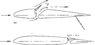
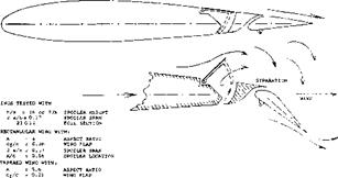
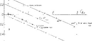
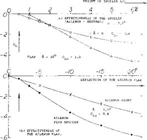
Slot-Lip Aileron. Ventilation can also be obtained by opening some kind of duct leading from the wing’s pressure side to behind the spoiler. In the so-called plug aileron, see figure 24, a ventilating slot is opened when the plug-shaped spoiler plate is projected from the upper surface. Another way of opening a slot is as in the original slot-lip aileron, an example of which is shown in figure 21,a. Effectiveness of this configuration is high; the time lag (see in figure 18) is considerably reduced. However, the duct leading through the wing is not very desirable and the drag added by the opening in the lower side (if left uncovered) reduces the efficiency of the wing. In an advanced form, as in part b of the illustration, the space ahead of a slotted wing flap is conveniently utilized. Results of slot-lip tests are as follows (see figure 21 ,c):
a) At very small deflection angles the slot lip has characteristics similar to, but poorer than those of, an ordinary aileron, as there may be a 5 or 10° dead range of deflection.
b) Upon exceeding a comparatively small upward deflection the slot lip causes the flow to break away from the upper side of the landing flap (if deflected), and the slot lip has the functions and characteristics as a true spoiler.
c) Separation as under (b) must be expected to take place suddenly, say at 6 = —5°.
d) Effectiveness is much higher for 60° flap deflection than for neutral position.
e) Hinge moments are irregular, particularly for neutral wing-flap position because of the separation as under
(c) .
f) Drag increases with upward slot-lip deflection in a manner similar to that of the split-flap aileron described in a preceding section, thus providing a desirable positive component of yawing moment, see part
(d) of figure 21.
In conclusion, this type of slot-lip aileron (as other spoiler types located near the trailing edge) is found to be sufficiently effective in combination with a deflected wing flap. It seems to be unsatisfactory, however, without such deflection.
|
|
|
|
Figure 21. Two versions of the slot-lip spoiler (9).
a) Original slot-lip configuration (9,e, h).
b) Combination with slotted wing flap.
c) Lift coefficient of (b) as a function of slot-lip deflection.
d) Section drag coefficient associated with slot-lip deflection.
 |
 |
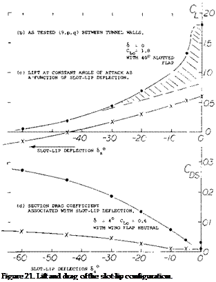
Figure 20. Characteristics of suction-side spoilers as a function of their location along the foil-section chord.
a) Time lag measured to the point where the reduced lift level is reached.
b) Effectiveness obtained for an original undisturbed lift coefficient CLO = 1.0.
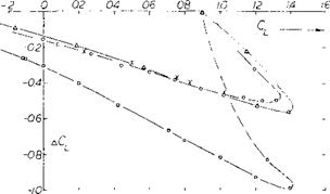
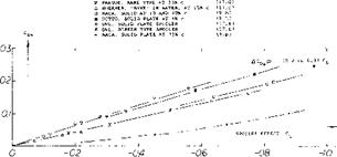
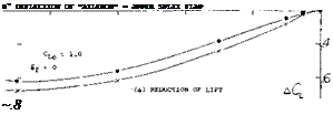
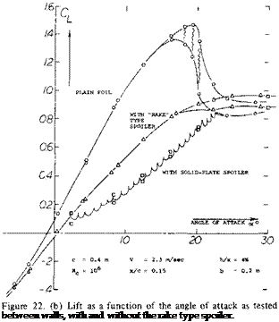 Effectiveness as a Function of Lift. The lift coefficient of a foil section is presented in figure 22 without and with a rake-type spoiler projected from the upper side. It is seen that the differential of the lift coefficient increases with the original (undisturbed) value of that coefficient. It is also evident that for constant spoiler projection, the lift curve slope is appreciably reduced. Lift differentials are plotted in figure 23 as a function of the original lift coefficient. At CL0 = zero, there is evidently some negative lift caused by the projection of spoilers from the upper side of the wings or foil sections tested. This is thus an example where the spoiler produces lift, rather than destroying lift. As the lift coefficient is increased the differentials grow along straight lines. It should also be noted that the spoiler effectiveness does not discontinue at or beyond the maximum lift coefficient. The effectiveness reduces, however, and it reaches zero at an angle of attack where the flow is really separated from the suction side.
|
|
|
|||||||||||||
|
|||||||||||||
|
|||||||||||||
|
|||||||||||||
|
|||||||||||||
|
|||||||||||||
|
|||||||||||||

![]()

Figure 22. Rake-type Spoiler.
a) Configuration and spoiler shapes as tested in a water tunnel (17, c).
b) Lift as a function of the angle of attack.
c) Experimental full-scale installation (17,c) in Ju-88, tested for
(18) Characteristics of slot-lip ailerons & plug-type spoilers:
(a) Weick, Tunnel Tests, NACA TN 547 (1935).
(b) Shortal, Flight Tests, NACA T Rpt 602.
(c) See NACA Tech Reports 443 and 605; and (7,k).
(d) NACA TN 547 and 1079.
(e) Rag alio, With Full-Span Flaps, J. A.Sci. 1950 p.
(0 Fischel, Plug Spoiler Brake, NACA T Rpt 1034 (1951; also T Notes 1473,1663,1802,1872 (1948/49).
(19) The Ju-288 was a high-speed bomber during World War II:
(a) Jane’s All the World’s Aircraft.
(b) Hoerner, Spoiler Control System, Dr.-Ing. habil. Thesis, 1941.
The helix angle at 100 mph = 147 ft/sec, is:
u/V = p b/2V = 0.6 (34)/(2 147) w 0.07 = 4°
This value is near the lower boundary of the range as indicated in equation 103. Results reported in (4,a) show in a similar manner rolling performance of a P-61 airplane, as follows:
wing span spoiler span spoiler location height of spoiler
At a speed of 334 mph = 490 ft/sec the rolling velocity obtained was
34 degrees/sec for spoiler alone
50 degrees/sec for spoiler plus aileron.
The small guide ailerons used (at the wing tips) were deflected to plus/minus 15°, where the stick force reached 80 or 85 lb. The helix angle corresponding to the rolling velocities listed are 0.04 and 0.06, respectively.
|
|
|
RAKE-TYPE SPOILERS) о "COMB" ON 23012 (17,c) h = 5.7% c at x = 0.15c 4 RAKE IN WATER TUNNEL (17,c) h = 4% c at x = 0.15c x IN PRAGUE WIND TUNNEL (17,d) h = 6% c at X = 0.33c |
SOLID PLATE TYPE:
a ON 23012 FOIL (9,h) h = 5% c at x = 0.20c
Figure 23. Effectiveness of spoiler control as a function of the lift coefficient at which the spoiler is used.
Spoilers in Presence of Wing Flaps. In regard to effectiveness we have seen that:
a) spoilers will be most effective when used in combination with a more or less round-nosed, cambered, high – lift foil section.
b) the effectiveness grows with the lift coefficient at which the spoiler is used.
When projecting a spoiler from the upper side of a wing, the flow will also be disturbed where it passes the wing or aileron flap (if there is one), and the spoiler will make the flow break away from a deflected trailing edge wing flap (provided that the flow was still attached). This is particularly true in the case of a slotted flap as demonstrated in figure 21,e, where the shaded area is due to separation from the flap, while the function CL (cfs ) with the flap in neutral position, represents the ordinary spoiler effect.
(20) Lateral control wing spoilers, flight-tested:
(a) Weick, Rolling Moments, NACA T Rpt 494 (1934).
(b) Soule, With Full-Span Flaps, NACA T Rpt 517 (1935).
(c) Wetmore, Retractable Ailerons, NACA TN 714 (1939).
(d) Shortal, Slot-Lip Spoiler, NACA T Rpt 602 (1937).
(e) Fikes, Plug on Swept Wing, NACA RM L52A03 (1934).
(f) Gilruth, Lateral Requirements, NACA T Rpt 715 (1941).
(g) Sphor, Spoiler Arrangements, NACA TN 1123 (1947).
Flap Flow. An arrangement similar to the slot-lip spoiler is the plug type, mentioned before in connection with time lag and ventilation. Figure 24 presents shape and the principle characterisitcs of a configuration of this type. We see in particular:
a) that the rolling moment increases with the lift coefficient, at which the spoiler is used,
b) that the effectiveness is higher with, and it grows with, the deflection angle of a slotted lift flap.
c) that effectiveness reaches a maximum at a flap angle in the order of 40°.
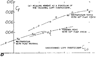
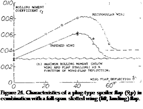 The type of flap flow, whether attached or separated, is of basic importance. Any plug-type of slot-lip spoiler cannot destroy much lift produced at and due to the wing flap, unless the flow is attached to its upper or suction side. It must be concluded, accordingly, that any spoiler, when used in combination with a trailing-edge split flap (behind which the flow is always separated), will only have an
|
2 a/b ~ 0.45 SPOILER SPAN x/c = 0.66 SPOILER LOCATION |
effectiveness somehow equal to that with the wing flap in neutral position. For illustration, see the effectiveness of the plug-type spoiler in figure 24 in presence of a wing flap deflected to 50° (where the flow must be assumed to be separated from the suction side of the flap). The high values of the lift reducing effect as in figure 21,c up to ACl = —1.7 can also partly be attributed to a reduction of the foil-section circulation because of the slot opened up ahead of the lift flap. Including flow separation from a slotted flap deflected between 20 and 40°, the slot lip as in figure 21,b has an effectiveness, measured in the form of (ACl), between —1.5 and —1.8 at undisturbed lift coefficients Cl0 between 1.1 and 2.7. Such values are roughly 2 times those of the solid-plate and some 3 times the maximum of those of the rake-type spoilers as in figure 23. Thus destroying practically all of the lift produced by the foil section as well as by flap deflection, the slot-lip spoiler appears to be extremely effective at higher lift coefficients.
Induced Yawing Moments. When changing the lift coefficient in the part of the wing span covered by an aileron flap or a spoiler, by a certain ACU, the induced drag for that part is calculated using equation 15 . As mentioned before (in connection with the Frise-type aileron), the significance of this differential rests in the fact that it causes a yawing moment the direction of which is opposed to the motion of an airplane when making a turn. Since the rolling moment is the result of the lift differential ACL, and the yawing moment is proportional to ACDl , we obtain the moment ratio as in equation 17. We have evaluated that equation for an aspect ratio A = 4. Experimental results plotted in figure 25 confirm the analysis well, when considering a small positive and constant component evidently reflecting the variation of the viscous foil section drag as a function of flap deflection.
|
|
|
04- Qy Ct |
|
(a) • EQU. (9) FOR A = 4 |
|
0.6- 1 1 J |
|
Figure 25. The variation of the yawing moment of rectangular aspect-ratio-4 wings, presented in the form of the moment ratio C„j/Cjl as a function of the lift coefficient at which lateral control is applied: a) as indicated by theory (see text) b) due to plain aileron deflection c) due to a “plug” spoiler while 6=0 d) due to a spoiler in presence of a slotted wing flap deflected to 30 and 40 . |
|
Figure 26. Parasitic drag associated with the lift differential produced by various suction-side spoiler devices. |
Parasite Drag. When deflecting a spoiler, the flow past the suction side of the airfoil section separates. As a result of this separation there is an increase of parasite drag. Drag coefficients tested on rectangular wing models equipped with full-span suction-side spoilers are plotted in figure 26. The section drag increases in proportion to the lift differential caused by the various types of spoilers tested. Therefore:
ACds = — к (ACl ) (23)
 |
where к is between 0.2 and 0.3 for forward spoiler locations between 0.1 and 0.3 or 0.4 of the chord. There is one example in the graph, representing a plug-type or slot-lip spoiler, at a location x = 0.73 c. The factor к is only 0.1 in this case. The increase in parasite drag due to spoiler deflection results in an increase in the yaw to roll moment coefficients (into the more or less desirable positive range) by an amount of ~ 0.2, on account of a plug-type spoiler located at x = 0.56 of the chord, figure 25. Note that the moment ratio is equivalent to the factor к in the last equation. When using spoilers in combination with slotted wing flaps (at deflection angles such as 30 or 40 where the flow is still attached to their suction side) the parasite drag due to spoiler projection is almost doubled. The factor equal to the moment ratio is between 0.3 and 0.4. In conclusion, spoilers present a usually desirable positive contribution to the yawing moment when turning an airplane. It is conceivable, however, that the positive due-to-spoiler yawing moment might be too large at smaller lift coefficients, particularly when diving an airplane at or close to CL = zero.
Combination With Aileron Flap. We have seen that spoilers have comparatively high effectiveness at higher lift coefficients, particularly when used in combination with a lifting (slotted) wing flap. Spoilers may also reduce the yawing caused by the rolling moment produced in the wing to zero. Combination of a spoiler with a pair of possibly small-span ailerons promises advantages as follows:
Flight Testing. Wind and water tunnel investigations of the comb or rake type suction-side spoilers (as in figures 22 or 27) show among others:
a) that effectiveness is high in comparison to more downstream locations.
b) that time lag (delay) is small, but still twice that of a conventional aileron.
![]()
a) The ailerons will eliminate or sufficiently cover the time lag associated with plain spoiler operation.
b) The ailerons will also cover the dead range of their projection (such as found in figures 21,c and 27,a).
c) Ailerons will provide a desirable amount of hinge and control moment, which retractable arc-type spoilers do not have.
d) In regard to yawing moments, a suitable combination of spoiler and aileron flaps may provide the most desirable or most acceptable solution.
e) While ailerons do not function well in combination with full-span flaps, spoilers will work particularly well when placed in front of wing flaps.
An example of a lateral control system in which a short aileron is combined with a spoiler is presented in figure 28.
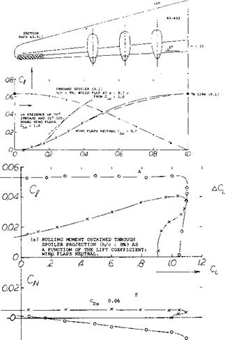
Spoiler and Plain Flap. The experimental results in figure 27 confirm the fact that (without presence of a deflected lift flap) a spoiler may not have sufficient effectiveness. Roughly, the rolling moment produced by a spoiler (projected on the upper side of the foil section) is equal to that due to deflection of an aileron flap on one side of the wing. Consequently, when using a pair of aileron flaps, their combined power will be twice that of the spoiler. Using now the spoiler together with an aileron flap located behind, in the same part of the wing span, figure 27 shows that their combined effectiveness is somewhat less than the sum of their individual powers.
Spoiler Span. The model of a large 6-engine airplane was investigated as to lateral control (9m). When increasing in steps the spanwise length of a screen-type spoiler, at 0.65 chord, the rolling moment produced increases as shown in figure 28,a. For comparison, results for another series of spoilers are also plotted in the graph, beginning in the center of the wing. The function obtained is very similar to that in figure 4. Regarding yawing moments, figure 28,b shows a positive value corresponding to an increment of the section drag coefficient by ACD5 ^ 0.06. The moment due to control by means of the short-span aileron flap is, on the other hand, negative (see equations 16 and 17). Figure 28,b also illustrates the fact that a spoiler produces a rolling moment roughly equal to that of a one-side aileron flap.
A combination of rake type spoiler with a slotted wing flap and with an independent short-span aileron was subsequently flight-tested, in 1941, on the Ju-88 airplane. In comparison to the original condition of the airplane, the span of the ailerons was reduced to half (the wing flaps were extended, accordingly). Results are as follows:
a) At higher lift coefficients, lateral control effectiveness is higher than that of the original configuration.
b) At higher speeds (i. e. at lesser lift coefficients) control effectiveness is lower than in the original condition; effectiveness is fully satisfactory, however.
c) The spoiler’s positive yawing-moment component increases the control effectiveness, by avoiding yawing in the wrong direction.
d) Positive yawing moments also improve handling qualities in turns, when maneuvering only one of two engines, and during blind flying (on instruments).
|
The foil, flap and spoiler configuration tested is as in figure 19. There are 30 prongs in a piece of span equal to the chord. The clearance between the prongs is 0.4 of their spacing, so that the spoiler solidity is 60%. |
Figure 27. Effectiveness of spoiler and aileron flap as tested (17,c, d) full-span on a rectangular wing model with A = 2.6.
Jet Spoiler. Another method of spoiling the suction-side flow of an airfoil is by means of a jet discharging at a suitable location. Devices of this type are described in (21). The spoiling effect of the jet sheet is expected to be a function of the momentum coefficient
Cu = (w/v)2 (s/c) (bs/b) (24)
where w = jet velocity, s = width of the slot from which the jet issues, and b5 = spanwise length of that slot. It is said in the second of two reports (21,a), however, that “aerodynamic time lag may not be any less than for mechanical spoilers”. It is obvious that a jet sheet could as well be issued from the trailing edge of a wing thus forming a jet flap aileron, presumably with characteristics similar to those of mechanical flaps.
|
|
|
-0.2 і |
|
(b) YAWING MOMENTS ASSOCIATED WITH THE ROLLING MOMENTS ABOVE. |
ROLLING AND YAWING MOMENTS AS A FUNCTION OF THE LIFT COEFFICIENT, CAUSED BY:
(A) PAIR OF SHORT AILERONS WITH SPAN RATIO 2 a/b = 0.13 (S) SPOILER AS ILLUSTRATED IN (a) WITH 2 a/b = 0.35.,
Figure 28. (a) Configuration tested (9,m) at Rc = 9(10)6; and rolling moment caused by spoiler projection (h/c = 8%) as a function of the span ratio 2 a/b. For comparison one-side aileron with full outboard span 2 a/b = 0.41.
(b) Rolling moment coefficient of a 6-engine pusher-type airplane model (9,m).


