Concept of the Boundary Layer
At low angles of attack, the effects of viscosity are confined to a thin region near the surface of the airfoil known as the boundary layer. Historically, the concept of the boundary layer was first proposed by Prandtl (1928) in his seminal work on the subject. Real fluids do not slip at a solid boundary and there will be no relative motion between the fluid and the surface of the airfoil. Therefore, there is a region close to the airfoil where the velocity rises from zero at the surface to the external flow velocity, Ue. This boundary layer region is generally very thin, being a small fraction of the airfoil chord. The concept is illustrated in Fig. 7.3. On an airfoil operated at higher Reynolds numbers the boundary layer will generally vary from practically zero thickness near the leading edge to a few percentages of the chord at the trailing edge. At lower Reynolds numbers the boundary layer can be much thicker, which will result also in the airfoil having a higher a profile drag.
Boundary layers are found to be of two main types: laminar or turbulent. A third type can be considered to be transitional, although this is not a steady boundary layer flow and is difficult to characterize. A comparison of the profile shapes of a laminar and turbulent boundary layer is also shown in Fig. 7.3. The parameter 5 is the boundary layer thickness, which is defined as the value of у for which 99% of the external flow velocity is recovered (i. e., и = 0.99Ue). The flow in a laminar boundary layer is smooth and free of any mixing of fluid between successive layers, whereas the flow in a turbulent boundary layer is characterized by significant mixing between layers of the fluid. This produces a momentum transfer through the boundary layer, and so the distribution of velocity in a turbulent boundary layer is characterized by larger velocities closer to the airfoil surface. Also, for the same reasons, a turbulent boundary layer has a greater thickness compared with a laminar boundary layer that develops under the same pressure gradient. See Schlichting (1979) and Young (1989).
Viscous stresses are produced whenever there is relative motion between adjacent fluid elements, and these stresses produce a resistance that tends to retard the motion of the fluid. The viscous shear stress, t, is related to the absolute viscosity, /x, by Newton’s formula
where du/dy is the rate at which the flow velocity increases perpendicular to the airfoil surface. (Note that the partial derivative is used in this equation because и can vary not only with у but also in other directions.) Thus, as implied by the shape of the boundary layer velocity profile in Fig. 7.3, the shear stress, rw, produced on the surface of an airfoil will be greater with a turbulent boundary layer than for a laminar one because
Ґ du
(7J)
The development of a laminar boundary layer in a zero pressure gradient flow can be computed exactly. This result was first obtained by Blasius (1908), with an improved solution by Kuo (1953). In Blasius’s solution the local skin friction coefficient, Cf, on one side of a flat-plate is
cf = = 0.664 Re~° (7.8)
1 inV2
2 r oo
where Rex is the Reynolds number based on the distance from the leading edge of the plate. The net shear stress drag coefficient of the plate will be
2 rc
Cd = – / cf dx = 1.328 Re~0 5, (7.9)
c Jo
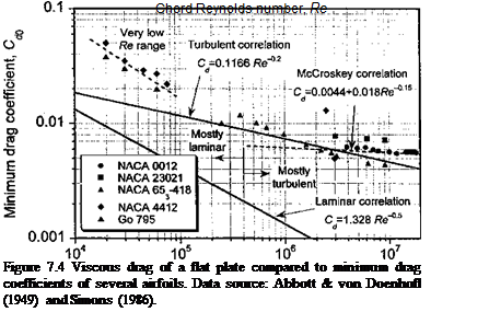
where c is the chord of the plate. This result is plotted in Fig. 7.4; however, very few airfoils follow the Blasius result because at Reynolds numbers above about 5 x 10⁵ the boundary layer usually becomes turbulent even at low angles of attack. The reason for this is that at Reynolds numbers above a certain minimum value, natural flow disturbances (although often caused premature! у by surface roughness) can cause a transition from a laminar to a turbulent boundary layer. Helicopter airfoils will typically exhibit laminar flow only over a few percentages of the chord. For a fully developed turbulent boundary layer on a flat-plate, the skin friction coefficient Cf on one side of the plate is found to be close to
 |
cf =0.0583 Re~0 2, (7.10)
so that
2 Cc
Cd = – Cfdx = 0.1166 Re~0-2. (7.11)
c Jo
The validity of the latter expression is limited to a Re range between 105 and 109. Below Re = 5 x 10⁵ the boundary layer can normally be assumed to be laminar unless artificially tripped. The drag of a flat-plate with a fully turbulent boundary layer is also plotted in Fig. 7.4 and is compared to the measured minimum drag coefficients of several airfoils. The results suggest that the turbulent flat-plate solution is a good approximation to the viscous (shear) drag on airfoils over the practical range of Reynolds numbers to be found on helicopters, that is, above about 106. In this case it will be sufficient to assume that
![]()
 (7.12)
where Re ref is the reference Reynolds number for which a reference value of drag C^ref is known. The empirical equation (Eq. 6.20) suggested by McCroskey (1977) offers an improved correlation for airfoils with fully developed turbulent boundary layers at the higher Reynolds numbers. At very low Reynolds numbers, say below 105, the laminar boundary layer separates more readily and the profile drag of typical airfoils are much larger that either laminar or turbulent boundary layer theory would suggest. Airfoil behavior in this Reynolds number regime is important for many classes of micro air vehicles (see Section 6.14). In this case, changing the scaling coefficient from 0.2 to 0.4 in Eq. 7.12 is good approximation based on the results shown in Fig. 7.4 at very low Re.
Leading edge Trailing edge
|
|
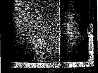
Figure 7.5 Surface flow visualization on a airfoil at low AoA showing the transition from a laminar to turbulent boundary layer. Eppler 387 airfoil, Re = 350,000, a = 2°. (Photo courtesy of Michael Sellig.)
point
Note also that a turbulent boundary layer will be thicker than a laminar one. If 8 is defined as the value where и = 0.99Ue then for a laminar boundary layer
![]()
![]() 8 ~ 5.2* Re-° and for a turbulent boundary layer 8 ~ 0.37* Re~0-2.
8 ~ 5.2* Re-° and for a turbulent boundary layer 8 ~ 0.37* Re~0-2.
Therefore, in addition to a higher viscous shear on the airfoil surface the presence of a

 |
tnrKnlpnt КлппЛііп/ Ь/рг will rpcnlt in я orpQfpr u/яігр mnmpntnm Hpfirit япН я ЫоЬрг
………………………………………………………………………………. ij TTXXX 1VOM1V ХХЖ W 4«V***W*W^*« V^WXX-W’XV UUS* V* overall profile drag compared to an airfoil with a fully laminar boundary layer.
The significance of the two boundary layer states on an airfoil at low AoA and relatively low Reynolds number is illustrated in Fig. 7.5. The flow was visualized by means of the surface oil flow technique (see also Fig. 7.31). For these conditions the forward 60% of the airfoil has a laminar boundary layer. The low surface shear stress here allows the oil to accumulate, especially near mid-chord, where the boundary layer approaches the point of separation. After laminar separation occurs, the flow will temporarily leave the airfoil surface but undergo a transition process and immediately reattach again as a turbulent boundary layer. This can leave a small region of recirculating separated flow that is known as a laminar separation bubble, as shown schematically in Fig. 7.6. The presence of laminar separation bubbles can also be observed by a small constant pressure region in the measurement of the chordwise pressure distribution near the leading edge of the airfoil. With surface oil flow visualization, the bubble is evidenced by an accumulation of oil – see Fig. 7.5 and later in Fig. 7.30. The formation of laminar separation bubbles is common for the types of airfoils and Reynolds numbers found on helicopter rotors. Further details on laminar separation bubbles are given by Ward (1963), Horton (1967), and Liebeck (1992).
It is found that the developing boundary layer on an airfoil is sensitive to the pressure gradient. In the boundary layer, a simplified form of the Navier-Stokes equations applies – see Section 14.2.1. In this case the equations are written in a classic form as
|
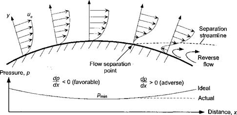
Figure 7.7 Development of the boundary layer in a simple external pressure gradient. |
—— = 0 (pressure gradient normal to surface). (7.17)
The pressure gradient is denoted by dp/dx along the surface. When the gradient is positive or adverse, that is, one in which dp/dx > 0, the pressure force is in the direction that tries to decelerate the flow. The resulting force on the fluid is particularly strong near the surface of the airfoil where the velocity is low; therefore du/dy near у = 0 becomes smaller the longer the adverse pressure gradient persists. This effect is shown in Fig. 7.7. At some distance downstream a point is reached where rw -» 0 and the direction of the flow reverses near the surface. This point is called the flow separation point, because the flow breaks away and leaves the surface, altering the entire disposition of the flow. Under these conditions, the concept of the boundary layer breaks down and a recirculating flow (wake) is left downstream of the separation point; downstream of separation the effects of viscosity influence an extensive region of the flow. Flow separation is one of the least well understood and poorly modeled phenomena in fluid mechanics, even under steady 2-D conditions. In unsteady (external) flows, the onset of flow separation is more complicated and there can be significant regions of flow reversal within the boundary layer even in the absence of separation – see McCroskey (1977). On rotating blades there are additional centrifugal and Coriolis acceleration terms acting on the 3-D boundary layer, which can affect stall behavior – see Section 13.12.2.
Turbulent boundary layers are much less susceptible to separation than laminar boundary layers because of the higher mixing and interlayer momentum transfer of the fluid. At higher Reynolds numbers, the pressure rise required to separate a turbulent boundary layer may be an order of magnitude iarger than that required to separate a laminar boundary layer. On rotor airfoils, which tend to have relatively sharp leading edges and peak suction pressures close to the leading edge, a steep adverse pressure gradient is found over most of the chord, and a laminar boundary layer can only exist for a very short distance from the stagnation point (typically, 2-15% chord). At low angles of attack, the turbulent boundary layer will generally extend all the way to the trailing edge of the airfoil. At higher angles of attack, the increasing intensity of the adverse pressure gradients will ultimately cause the turbulent boundary layer to begin to separate – see Thwaites (1960). Many rotor airfoils stall by the process of progressive turbulent trailing edge flow separation, whereby the separation
![]()

 Shear
Shear
layer
 |
7
Shear
layer
Figure 7.8 Development of trailing edge flow separation on an airfoil.
point starts at the trailing edge and moves forward on the chord with increasing AoA. This process is shown schematically in Fig. 7.8. When the airfoil forces and moments are plotted versus AoA, the onset of progressive trailing edge flow separation has a deleterious effect on the airfoil performance compared to that obtained with fully attached flow (see Section 7.9).


