
Our heavyweight helicopter equal in the world does not have
In Rostov started production of the most load-lifting rotary-wing car The Russian holding «Helicopt[...]

Everything about aircrafts and helicopters. News and events in aviation worldwide. Civil, transportation, military helicopters and airplanes.

Everything about aircrafts and helicopters. News and events in aviation worldwide. Civil, transportation, military helicopters and airplanes.

Everything about aircrafts and helicopters. News and events in aviation worldwide. Civil, transportation, military helicopters and airplanes.

Everything about aircrafts and helicopters. News and events in aviation worldwide. Civil, transportation, military helicopters and airplanes.


All parts of a model, including wings, tail fuselage and every component exposed to the air flow, contribute drag. Even the insides of cowlings, wheel fairings, etc., will add some drag if air passes through them. As with lift, the actual drag force generated depends on flight velocity, air density, size and shape of the model. The drag coefficient, like the lift coefficient, sums up all the features of the model and is a measure of its aerodynamic ‘cleanliness’. The formula is of the same type as that for lift:
DRAG = D = V4xpxV2xSxCD
The S, or area in this formula is normally the wing area of the whole aircraft. If the total surface area is used (including tail) for the Cl, the same total area must be used for the drag equation. This enables the drag and lift forces to be compared, usually in the form of
|
|
|
|
![]()
![]()
![]()
![]()
V+’kp V* = constant
Fig. 2.7 The venturi
a ratio, the lift to drag ratio or L/D. For level flight, lift will equal weight, which is constant (ignoring fuel consumption). Thrust can be increased or decreased by variations of throttle setting. This will change the drag force, since for level flight in equilibrium, thrust and drag are equal. At high speed, thrust is large and drag is large, but the total lift force remains the same, equal to the weight The ratio of lift to drag is low; drag has increased because of the high speed. At low speeds, still maintaining level flight, drag
 |
Fig. 2.9 Form or pressure drag
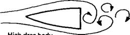 High drag body
27
reduces up to a point while lift still equals weight. Hence the L/D ratio increases. This improvement in drag force does not continue down to the slowest speed for any given model, since, as will appear, the total drag coefficient itself begins to increase rapidly at low speeds, and this is enough to outweigh the reduction in V. Hence at some speed the model achieves its maximum L/D ratio. The value of this ratio gives a rough measure of the all-round efficiency of the model.
As with lift, confusion arises if wind tunnel tests are wrongly interpreted. In tests of isolated bodies such as fuselages, wheels, etc., Де measure of size, S, used in the drag formula is Де cross sectional area of the object tested. This gives a wholly ffifferent result from Де drag coefficient of such items when Деу are related to Де wing area of a whole aircraft Whh wing drag figures from tunnel tests, Де same applies as to section lift coefficients. The real wing in flight does not reproduce Де test figures across Де whole span. It is hardly ever necessary to calculate the actual drag of model components. The main toing is to know how drag is caused and how to reduce it. Modellers quite often speak of increasing lift by changing Де trim or using a different wing section. In level flight the lift force equals Де weight and Дів remains true after Де trim or aerofoil change just as before. Hence akhough Де lift coefficient, Cl, may have been increased, Де lift force remains equal to Де weight in level flight. Every change of this kind however, does change Де drag of Де aircraft If the drag is regarded as Де inevitable price paid for keeping a given model in Де air, reducing the drag price always makes for a more efficient flight
