Flat Plate Airfoil
 Choose the circle with its center at the origin and (6-27),
M = /3 = 0
 |
 |
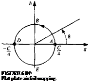
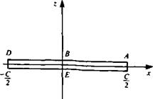
The circle is given by / = C/4e, e and the corresponding airfoil is Y = C cos в/2 which is seen to be a flat plate of chord c = C (see Fig. 6.10). Note that
0 < 0 < я represents the top surface and я<0<2л represents the bottom. The complex velocity on the plate surface is obtained using Eqs. (6.31) and (6.31a) as
![Flat Plate Airfoil Подпись: [sin a — sin (a — 0)] sin 0](/img/3130/image576_2.gif) |
||
2i’Q4sin a ~ sin (a – 6)]e~,e 2iQaa[sin a — sin (a — 6)]е~ів 1-е~ш 2i sin в е~ів
and since x — c/2 (cos 0) then sin 0 = ±Vl — (2x/c)2, and we have
![]() W. l-cos0 ll-2x/c
W. l-cos0 ll-2x/c
— = cos a + sin a—:—-— = cos a ± sin a -——- <2„ sin 0 V 1 + 2x/c
where the plus sign refers to the upper surface and the minus sign to the lower. Note that the trailing edge velocity is Q„ cos a and that the disturbance to the stream vanishes as the square root of distance from the trailing edge. Also, the velocity has a square root singularity at the plate’s sharp leading edge.
For small a, Eq. (6.35) becomes
![]() W „ 1 – cos 0
W „ 1 – cos 0
— = 1 + a———–
0» sin 0
Note that with the use of Eqs. (5.37), (5.48), and (5.71) (and considering the different definition of 0 in Chapter 5), the solution is identical to the flat plate solution from thin airfoil theory.
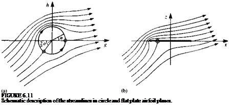
The streamline patterns in the circle and plate planes are shown schematically in Fig. 6.11. Note that the forward stagnation point in the circle plane is at 0 = л + 2a and therefore the forward stagnation point on the plate
 |
is at x = — c/2(sin 2ar).
The circulation and lift force are given by Eqs. (6.28) and (6.29) as
Г = ncQ„ sin a (6.36)
L = лpcQt sin a (6.37)
and the lift coefficient is (Eq. (6.29a))
С/ = 2л sin a (6.37a)


