Forces and Moment
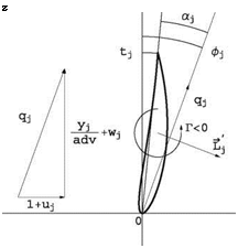
The flow is assumed to be inviscid, Cd = 0. At the blade element j the flow configuration is as depicted in Fig. 10.11.
The local incidence is
![]()
![]()
![]() (10.29)
(10.29)
where фj is called the flow angle and tj is the angle of twist at the element. The local lift coefficient is obtained from the result of thin airfoil theory or from an experimental or numerical profile lift curve C;(a). In thin airfoil theory, the lift is given by
d
Ci (a) = 2n(a + 2-) (10.30)
c
d is the profile mean camber defined as
where d (x) is the equation of the camber line. According to the Kutta-Joukowski lift theorem, the lift force per unit span is perpendicular to the incoming flow, its
Fig. 10.11 Blade element
 flow configuration
magnitude is L’ = pq Г and its orientation is 90° from the incoming flow direction, rotating opposite to the circulation. q = q = ^(1 + u)2 + (ad – + wj2 is the normalized magnitude of the incoming flow velocity vector. This can be expressed mathematically as
~L ‘ = pU~cf Л URr~-f (10.32)
where dimensionless quantities have been introduced. ~j is the unit vector along the y-axis and Г < 0in Fig. 10.11. Upon a dimensionalization of the lift, the circulation is obtained as
1
Г] = — qjcJci (a j) (10.33)
The contribution of the blade element to thrust and torque can now be derived. Projection in the x-direction gives
dTj = L j cos фJRdyJ = – pUqj cos фJURГJRdyJ = —pU2 R2 гД^- + w Д dyj
 |
or, upon integration
Projection of the lift force in the z-direction and accounting for the distance from the axis, the torque contribution reads
dTj = L’j sinфjRyjRdyj = pUqj sin ф^ URFjRyjRdyj = pU2R3rj (1 + Uj)yjdyj
(10.37)
which integrates to give
or, in dimensionless form
These results are for one blade. Total thrust and torque must account for all the blades.


