INFLUENCE OF HIGH-LIFT DEVICES ON TRIM AND PITCH STIFFNESS
Conventional airplanes utilize a wide range of aerodynamic devices for increasing These include various forms of trailing edge elements
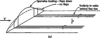
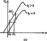
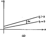
(plain flaps, split flaps, slotted flaps, etc.), leading edge elements (drooped nose, slats, slots, etc.) and purely fluid mechanical solutions such as boundary layer control by blowing. Each of these has its own characteristic effects on the lift and pitching moment curves, and it is not feasible to go into them in depth here. The specific changes that result from the “configuration-type” devices, i. e. flaps, slots, etc., can always be incorporated by making the appropriate changes to Cm^ and CLm in (6.3,4) and following through the consequences. Consider for example the common case of part-span trailing edge flaps on a conventional tailed airplane. The main aerodynamic effects of such flaps are illustrated in Fig. 7.3.f
1. Their deflection distorts the shape of the span wise distribution of lift on the wing, increasing the vorticity behind the flap tips, as in (a).
2. They have the same effect locally as an increase in the wing-section camber, i. e. a negative increment in Cm and a positive increment in От.
"tob
3. The down wash at the tail is increased; both e0 and де/дк will in general change.
The change in wing-body Gm is obtained from (6.3,4) as
AC’*,, = ACm^n + AGLJh – hnJ (7.2,1)
The change in airplane CL is
АСь = ДОіюь-й(|д6 (7.2,2)
and the change in tail pitching moment is
AGmt = atVH Де (7.2,3)
When the increments ДG„ . and Д GT are constant with a, then the only
ma. c….. J-‘vtb ’ V
f Note that a is still the angle of attack of the zero-lift line of the basic configuration, and that the lift with flap deflected is not zero at zero a.

|

![]()


effect on CL and Gm is that of de/да., and from (6.3,31) and (6.3,34a) these are
A. a = ACLx=-at^ Ap (7.2,4)
о да
А<?та = (ft — KJ Aa + atVH A — (V.2,5)
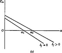
The net result on the CL and Gm curves is obviously very much configuration dependent. If the Cm — a relation were as in Fig. 7.3e, then the trim change would be very large, from oq at df = 0 to ot2 after flap deflection. The CL at a2 is much larger than at ax and hence if the flap operation is to take place without change of trim speed, a down-elevator deflection would be needed to reduce atrim to a3 (Fig. 7.3c). This would result in a nose-down rotation of the aircraft.


