INFLUENCE OF THE PROPULSIVE SYSTEM ON TRIM AND PITCH STIFFNESS
The influence of the propulsive system upon trim and stability may be both important and complex. The range of conditions to be considered in this connection is extremely wide. In the first place, there are several types of propulsive units in common use—reciprocating-engine-driven propellers, turbojets, propeller-jets, and rockets. In the second place, the operating condition may be anything from hovering to reentry. Finally, the variations in engine-plus-vehicle geometry are very great. The analyst may have to deal with such widely divergent cases as a high-aspect-ratio straight-winged airplane with six wing-mounted counterrotating propellers or a low-aspect – ratio delta with buried jet engines. Owing to its complexity, a definite and comprehensive treatment of propulsive system influences on stability is not possible. There does not exist sufficient theoretical or empirical information to enable reliable predictions to be made under all the above-mentioned conditions. However, certain of the major effects of propellers and propulsive jets are sufficiently well understood to make it worth while to discuss them, and this is done in the following.
In a purely formal sense, of course, it is only necessary to add the appropriate direct effects, Gm and dCmJd& in (6.3,34 and 35), together with the indirect effects on the various wing-body and tail coefficients in order to calculate all the results with power on.
When calculating the trim curves (i. e. elevator angle, tab angle, and control force to trim) the thrust must be that required to maintain equilibrium at the condition of speed and angle of climb being investigated (see
Sec. 6.4). For example (see Fig. 6.1), for flight at speeds below about M = 3 (see Sec. 5.9) and assuming that a2. 1
Solving for CT, we get
CT = °D + °L tan 7 (7.3,2)
1 — ay tan у
Except for very steep climb angles, ay tan у 1, and we may write approximately,
CT = CD + CL tan у (7.3,3)
 |
Let the thrust line be offset by a distance zP from the C. G. (as in Fig. 7.5) and neglecting for the moment all other thrust contributions to the pitching

moment but Tzp, we have
|
|||||||||||||
|
|||||||||||||
|
|||||||||||||
|
|||||||||||||
|
|||||||||||||
|
|||||||||||||
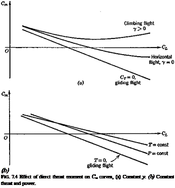
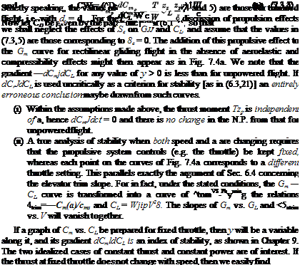
Thus in the constant thrust case, the power-off Cm — CL graph simply has its slope changed by the addition of thrust, and in the constant power case the shape is changed as well. The form of these changes is illustrated in Fig. 7.46 and it is evident by comparison with 7.4a that the behavior of dCmjdCL is quite different in these two situations.


