Modification Schemes, Application Aspects
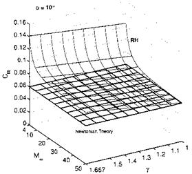
We have noted above, that already at free-stream Mach numbers above Мж « 3 to 4 useful results can be achieved with Newton’s theory. However, for both the flat plate and the sharp-nosed cone results of Newton’s theory lie somewhat below exact results, as long as we have finite Mach numbers and realistic ratios of specific heats. What about the situation then at generally shaped, and in particular blunt-nosed bodies?
Two modification schemes to the original formulation have been proposed. The first is Busemann’s centrifugal correction [39, 22], which, however is not very effective.
The second scheme is important especially for blunt-nosed bodies. In [40] it is observed from experimental data, that for such bodies a pressure coefficient, corrected with the stagnation-point value cPmax, gives satisfactory results for Мж ^ 2.
With cPmax = cPt2 for the stagnation point, eq. (6.65), writing pe for the pressure on the body surface, respectively the boundary-layer edge, and using
![]()
|
вь, Fig. 6.37, for the local body slope, instead of a, we find the “modified” Newton relation
This modified Newton relation, in contrast to the original one, depends on the free-stream Mach number MTO.
For the investigation of boundary-layer properties, Section 7.2, at the stagnation point of blunt bodies or at the attachment line of blunt swept leading edges etc., we need the gradient of the external inviscid velocity ue there.
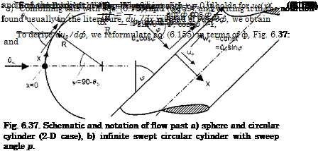
Assuming either a spherical or a cylindrical contour, Fig. 6.37 a), we find for both of them, see, e. g., [41], the Euler equation for the ф direction:
![]() 1 due
1 due
peUeR~W

At the stagnation point it holds
and hence
We substitute now ue in eq. (6.162) with the help of eq. (6.164) and q with the help of eq. (6.160), and find with eqs. (6.158) and (6.159)
where ps and ps are pressure and density in the stagnation point. Note that cp did cancel out.
pmax
The gradient of the inviscid velocity at the stagnation point in x – direction, Fig. (6.37), finally is
This result holds, in analogy to potential theory, with к = 1 for the sphere, and к = 1.33 for the circular cylinder (2-D case), and for both Newton and modified Newton flow.[76]
At the infinite swept cylinder with sweep angle p, it is the component of the free-stream vector normal to the cylinder axis, ucos p, Fig. 6.37 b), which matters. It can be written in terms of the unswept case and cos p:
![]()
![]() . (6.167)
. (6.167)
^ = 0
The important result in all cases is that the velocity gradient due/dx at the stagnation point or at the stagnation line, is ж 1/R. The larger R, the smaller is the gradient. At the attachment line of the infinite swept cylinder it reduces also with increasing sweep angle, i. e., due/dxlx=0,v>0 ж cosp/R.
We note finally that recent experimental work has shown, that the above result has deficiencies, which are due to high-temperature real-gas effects [43]. With increasing density ratio across the shock, i. e., decreasing shock stand-off distance, Sub-Section 6.4.1, due/dxlx=0 becomes larger. The increment grows nearly linearly up to 30 per cent for density ratios up to 12. If due/dxlx=0 is needed with high accuracy, this effect must be taken into account.
We can determine now, besides the pressure at the stagnation point and at the body surface, also the inviscid velocity gradient at the stagnation point or across the attachment line of infinite swept circular cylinders. With the relations for isentropic expansion, starting from the stagnation point, it is possible to compute the distribution of the inviscid velocity, as well as the temperature and the density at the surface of the body. With these data, and
with the help of boundary-layer relations, wall shear stress, heat flux in the gas at the wall etc. can be obtained.
This is possible also for surfaces of three-dimensional bodies, with a stepwise marching downstream, depending on the surface paneling [34]. Of course, surface portions lying in the shadow of upstream portions, for example the upper side of a flight vehicle at angle of attack, cannot be treated. In the approximate method HOTSOSE [34], the modified Newton scheme is combined with the Prandtl-Meyer expansion and the oblique-shock relations in order to overcome this shortcoming.
However, entropy-layer swallowing cannot be taken into account, because the bow-shock shape is not known. Hence the streamlines of the inviscid flow field between the bow-shock shape and the body surface and their entropy values cannot be determined.
This leads us to another limitation of the modified Newton method. It is exact only if the stagnation point is hit by the streamline which crossed the locally normal shock surface, Fig. 6.22 a). If we have the asymmetric situation shown in Fig. 6.22 b), we cannot determine the pressure coefficient in the stagnation point, because we do not know where Pi lies on the bow – shock surface. Hence we cannot apply eq. (6.99). In such cases the modified Newton method, eq. (6.155), will give acceptable results only if Pi can be assumed to lie in the vicinity of Pq.
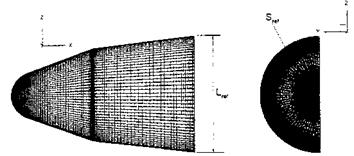
We discuss finally a HOTSOSE result for the axisymmetric biconic reentry capsule shown in Fig. 6.38.
|
Fig. 6.38. Configuration and HOTSOSE mesh of the biconic re-entry capsule (BRC) [34]. |
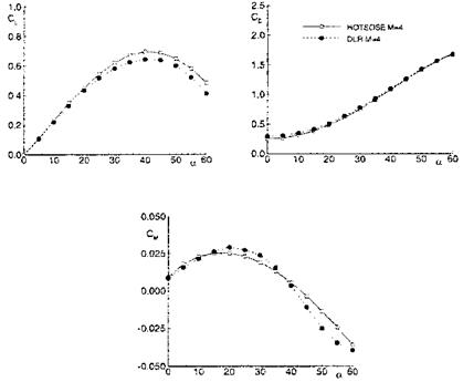
The scheme was applied for free-stream Mach numbers = 4 to 10 and the large range of angles of attack 0 ^ a ^ 60°. We show here only the results for Mж = 4, which are compared in Fig. 6.39 with Euler results.
The lift coefficient Cl found with HOTSOSE compares well with the Euler data up to a & 20°. The same is true for the pitching-moment coefficient Cm. For larger angles of attack the stagnation point moves away from the spherical nose cap and the solution runs into the problem that Pi becomes different from Pq, Fig. 6.22 b). In addition three-dimensional effects play a role, which
|
Fig. 6.39. Aerodynamic coefficients (inviscid flow, perfect gas) for the biconic reentry capsule at Mo = 4 obtained with HOTSOSE (o) and compared with Euler results (•) [34]. Upper part left: lift coefficient Cl, upper part right: drag coefficient Cd, lower part: moment coefficient Cm. |
are not captured properly by the scheme if the surface discretization remains fixed [34]. The drag coefficient Cd compares well for the whole range of angle of attack, with a little, inexplicable difference at small angles.


