Pneumatic and electronic scanning of multiple pressures
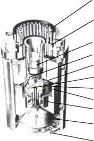
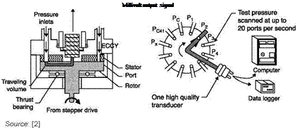
Before the production of cheap piezoresistive transducers, the use of a transducer for each of many pressure taps was considered too expensive; thus, pneumatic scanning valves, Scanivalve, were produced, from 1960 to 2000, connecting a single transducer of excellent quality with each of the pressure taps sequentially (Figure 1.10): the transducer is sequentially connected to the various Px ports by a single hole in the rotor which
Inside view of a Scanivalve and how it works


 Pressure transducer Typical port Elastic duct Collector hole Stator Rotor
Thrust Bearing
 |
Position transmitter (Encoder) electrically indicates port being measured Scanivalve drive (not shown)
terminates at the collector hole. As the rotor rotates, this collector passes under the Px input pressure ports in the stator. Because of the extremely small traveling volume, scanning rates of 20 ports per second are possible. The stator is elastically connected to the block in a manner which allows the stator to follow the surface of the rotor. Thus the pneumatic forces at each port, which tend to blow the rotor away from the stator, are withstood by the thrust ball bearing. Each Px pressure is elastically ducted from the block to its port in the stator.
Each valve can scan up to 48 pressure tubes and a single stepper motor can operate up to 5 valves. When one of the 48 ports is used for span and one for zero calibrating pressures, the pressure transducer can be automatically calibrated on every scan.
The Scanivalve is not suitable for a field survey of many rapidly varying pressures, in fact, the reading of each tap can only be done at each complete revolution, but even if the engine is stopped, reading of a variable pressure is affected by delays introduced by the pipe connecting the pressure tap and the Scanivalve, which has small diameter and considerable length. The size of the Scanivalve in fact prevents its accommodation within the model being tested.
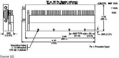
The advent of cheap piezoresistive transducers, with their qualities of high natural frequency and very small dimensions (in the order of mm) led to the creation of packages of transducers that can be accommodated within the models, e. g. a package of 64 transducers 105 mm x 36 mm x 14 mm in size (Figure 1.11). The scanning is done electronically and allows a sampling rate of up to 10 kHz per channel.
The reference pressure is sent simultaneously to all transducers. At each scan cycle it can be sent to a pressure transducer to control the calibration (Figure 1.12). At the same time cleaning of the pipe can be made to prevent clogging of the various tubes.

![]() Electronic pressure scanner with 64 transducers
Electronic pressure scanner with 64 transducers
 |
CAL 042 O. D.
 |
Source: [4]


