Separation effects
4.6 We have noted already (in Sections 4.3 and 4.4) that the theoretical treatment of the regions near the wing tips is generally rather poor: neither of the assumptions (4.51) nor (4.64) can really be justified
in those regions, whether the wing is swept or not, and the cbordwise loadings cannot really be expected to be like those on twodimensional aerofoils when the wing is unswept, or like those at a central kink when the wing is swept. Some improvement in the treatment of the tip regions of thick lifting wings with curved leading edges has been provided by H C Garner (1972). But there remain mathematical problems which have been discussed by К Stewartson
(1960) and by M van Dyke (1963). The problem has been treated in some detail by M Landahl (1968) for rectangular wing tips and by P F Jordan (1970) and
(1971) for parabolic tips (that is, planform shapes which can be approximated by a circle at the tip), making use of the solution for the lifting circular wing by W Kinner (1937). In both cases, departures from the classical solution were found and, in particular, the existence of a logarithmically – infinite upwash directly behind the wing tip. One line of thought could then be that this singularity should be, and could be, removed by an intense rolling – up of the free edge of the trailing vortex sheet. Steps in this direction have been made as long ago as 1932 by A Betz, by F L Westwater (1936), and again recently by D J Butter & G J Hancock (1971). In the simplest model, the continuous sheet is replaced by a finite number of line vortices, but this may lead to unreliable results, as shown by D W Moore (1971).
We note at this point that a flow model which includes a rolled-up vortex core will produce not only swirling velocities and hence a downwash on the wing but
also an axial velocity along the vortex core. This has been predicted by G К Batchelor (1964) and confirmed in comprehensive laboratory experiments by J H Olsen (1971). D W Moore & P G Saffman (1973) calculated in some detail the structure of laminar trailing vortices with an outer inviscid core and an inner viscous core. They found that the perturbation of the axial velocity in the viscous core can be either away from the wing or towards the wing, depending on the load distribution near the tip of the wing. For elliptic loading, the perturbation is towards the wing.
With a view to determining the effect of the trailing vortex sheet on the loading over the wing, В Maskew (1971) and T E Labrujere & H A Sytsma (1972) have extended their panel methods to take account of the rolling-up by an iterative procedure: the straight vortex filaments in the classical model are
replaced by small linear segments and the position and direction of these segments are then progressively adjusted until they are aligned with the streamlines of the mean motion. The results showed that the change in shape had little effect on the pressure distribution over the wing and thus left the mathematical problem unresolved. Perhaps the panel representation is too crude to bring such details into focus, or the classical model is quite adequate after all.
In reality, it is not this mathematical problem but a deficiency in the physics of the flow model, which requires attention. This concerns the actual position of the separation line: there is no reason to suppose that the flow
separates only from the trailing edge when the wing is put at an angle of incidence; the separation line can easily extend around the tip edge and creep up along it, especially if the edge is streamwise, as discussed in Section 3.3. The flow around the tip edge is then like that shown in Fig. 3.5(a) or, in an extreme case, like that sketched in Fig. 2.16. An ordinary separation line must be expected to be formed at a high-enough angle of incidence, depending on the detail of the shape of the wing tip. The trailing vortex sheet is then non-^planar, with near-vertical extensions at both tips. That such tip vortex sheets exist in a real flow was seen very early and clearly in observations by L Bairstow (1915)*) and by A Fage & L F G Simmons,
(1925) , but it was only in 1939 that A Betz proposed that tip vortex sheets should be taken into account in wing theory. The concept was then applied by К Mangier (1939). It is now clear that they matter in the tip region of wings of any aspect ratio and that they play an increasingly dominant part in the properties of wings as the aspect ratio is decreased. Thus the theories described in Section 4.3 are incomplete, to say the least.
What really happens near the wing tips can be seen from experimental results in Fig. 4.34 for the simple case of a rectangular wing of relatively high aspect ratio. The chordwise loading shows a large increase over the rear as the tip is approached, beyond that of the twodimensional section (dashed line) and the spanwise loading shows a second peak in the immediate neighbourhood of the tip, again with lift added to that calculated for the plain wing (dashed line). These additional loadings are consistent with a flow model where a vortex sheet springs from a separation line along the tip edge, rolls up along its free edge at the top, and joins the vortex sheet from the trailing edge; the velocities induced by such a sheet must produce additional suction pressures on the top surface of the wing just inboard of the tip. Along the tip
*see F W Lanchester (1915). Bairstow used flow pictures taken in a water tunnel for a square wing with strong tip vortex sheets in his (mistaken but very successful) attempt to discredit Lanchester’s theory of the classical wing.
![]()
163
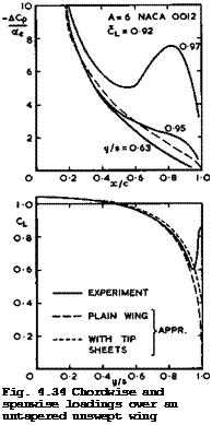
edge itself, the load falls to zero, i. e. the Kutta condition is fulfilled there.
There is as yet no adequate theory which is based on such a model of the flow. What exists is a numerical study by C Rehbach (1971) , which is based on a method by S M Belotserkovskii (1968); in this, the wing is represented by a vortex lattice and thus the trailing and tip vortex sheets by a series of discrete line vortices. This gives qualitatively plausible answers, but the rolling-up into cores cannot be adequately represented by isolated line vortices and the Kutta condition cannot be fulfilled. J Rom, H Portnoy &
C Zorea (1974) have also investigated the formation of wing-tip vortices, and J H В Smith (1975) has given a review of various theoretical attempts. Another theory by D KUchemann (1955) is based on Betz’s simplified model where the tip vortex sheets are assumed to be plane vertical surfaces. With the shape of the tip vortex sheets fixed in this way, the conditions that the free vortex sheet is a streamsurface and that it carries no pressure difference across it cannot be fulfilled, nor can the Kutta condition. But it may at least be assumed that the vorticity vector in the sheet lies, in some sense, in a "mean-flow" direction, namely, halfway between the direction of the mainstream and that of the tip chord inclined at an angle a, i. e. the vorticity vector is inclined at the angle a/2 to the mainstream. The height of the vortex sheet at the trailing edge is then
![]()
on rectangular wings, if the separation line along the tip edge of chord Cj starts at the leading edge. A further simplification is achieved by the assumption that the non-planar vortex sheet is such that the induced downwash ct£ is constant along the span and the vortex drag a minimum. The spanwise loading can then be determined from the flow in the Trefftz plane, as discussed in Section 3.2, assuming in addition that the shape of the trailing vortex sheet in the Trefftz plane is the same as that at the trailing edge. In fact, the procedure is the same as for a wing with solid endplates, for which this kind of theory has been developed by D Kiichemann & D J Kettle (1951) and J Weber (1954). This theory gives only the spanwise loading and the overall lift and drag.
When applied to wings of any aspect ratio with tip vortex sheets and combined with the RAE Standard Method, this approach leads to a non-linear variation of the lift with the angle of incidence because the height of the tip vortex sheet and hence the additional lift varies with a, by (4.111). Very simple relations obtain in the limiting case of rectangular wings of very small aspect ratio. The flow is then like that sketched in Fig. 2.16, but we must assume here that the flow remains steady and symmetrical about the longitudinal axis and that asymmetric vortex shedding does not occur. The change of the overall vortex drag and of the induced angle of incidence» from those given by (3.22) and (4.70) for the plain wing according to linearised theory, to those for the wing with tip vortex sheets, can be expressed by applying a factor Kv(h/s) < 1 to both these values, as in (3.38). (We cannot really
expect that the relation for the drag applies fully on wings with tip vortex sheets, whereas it might on wings with solid endplates where a sideforce acts on the endplate and a suction force on its leading edge). Since a
when A -*■ 0 , we have,
![]() 7Г ir A
7Г ir A
°L 2 KV “
The function Kv(h/s.) has been calculated by К Mangier (1939); it can be approximated by (3.39), so that
or
CL = -j Act + j a2 , (4.113)
using (4.111). This brings out clearly the non-linear lift increase above that obtained from linearised theory (first term in (4.113)). It also suggests that the linear term in (4.113) can be replaced by that from the linearised theory for wings of any aspect ratio. A theory on these lines has been developed by D KUchemann (1955) and (1956).
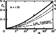
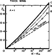
This theory has been applied to the cases shown in Fig. 4.34 and in curves (a) of Fig. 4.35. The spanwise loading then has a non-zero value at the wing tip, corresponding to the sideload on an actual endplate. But it will be seen that this theory does not reproduce the typical features of the actual loading. At best it can provide some estimate for the overall lift. This can be quite adequate if the flow separates only from the trailing and side edges and not also from the leading edge. It may be assumed that these conditions are realised in the tests of L Prandtl and A Betz (1920) in Fig. 4.35.
Properties of Classical and Swept Aircraft
When the flow separates also from the leading edge, as in the tests on thin flat plates carried out by 0 Flachsbart (1932), the theoretical model is obviously not adequate and the non-linear effects are even larger. The tip vor-
|
Л EXP. FLACHSBART (1932) THIN PLATE |
|
© EXP. PRANDTL-BETZ (1920)
Fig. 4.35 Overall lift of rectangular wings of small aspect ratio |
tex sheets can then be expected to be higher to begin with and then to grow more slowly with a . Therefore, J Weber (1955, unpublished) has proposed to use the relation
h/s “YcTVA (4.114)
instead of (4.111), which leads to
CL = I A a + a3/2 (4.115)
and curve (c) in Fig. 4.35. This fits Flachsbart’s experiments better.
A non-linear theory for wings of small aspect ratio with separation from all edges has been provided by W Bollay (1939). For the limiting case A -»* 0, this can be interpreted as representing a wing with a large bubble in its wake, extending to infinity (see D KUchemann (1956)). There is a secondary flow inside the bubble, which can again be thought of as being generated by plane vertical vortex sheets from the side edges, with the vorticity vector inclined at an angle ot/2 to the mainstream. The boundary condition is, as usual, that the wing together with the bubble should turn the mainstream through an angle a at the wing. In this model, to a first order, only the mass of air in front of the wing bounded by the two planes у = * s is turned; all the air outside these planes passes the wing by and remains undeflected. The lift
is then uniformly distributed over the wing and the lift coefficient is given by
CL = 2 sin2ct. (4.116)
As it happens, this is the same relation as that obtained from Newton’s model of a flow where the motion of the air particles is considered and assumed to be unaffected by a body until the particles hit it. The particles are then reflected from the surface without change of kinetic energy, and the pressure on the surface results from the rate of loss of normal momentum of the fluid on reflection. Newton’s relation is often considered to apply at hypersonic speeds, whereas it turns up here as an approximation for particular wings in incompressible flow for a model which has only some slight physical similarities with that of Newton. Values from (4.116) are shown as curves (b) in Fig. 4.35; they do not quite give a satisfactory approximation.
The relation (4.116) has also been derived by A Betz (1935) from yet another model of the flow. It applies in cases where separation also occurs along the leading edge, so that it may be assumed that the suction force there disappears and that CT ■» 0 in (3.29). In that case, the resultant air force in inviscid flow is normal to the wing surface and
L/D = 1/ tan a (4.117)
(see also Fig. 4.14). If the aspect ratio is very small, the resultant air force may be regarded as a cross flow drag of a twodimensional flat plate in a stream of velocity Vq sin a at right angles to it, with a crossflow drag coefficient Cdc . Thus the resultant air force normal to the wing is
R я CDc s ІР VQ2 sin2<x
Betz suggested that = 2 would be an adequate approximation, and this
 |
leads again to (4.116) for small a. The results in Fig. 4.35 indicate that Cqc could be somewhat greater than 2.
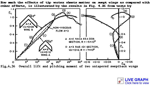
J F Cahill ASM Gottlieb (1950) and by J Weber & G G Brebner (1951) on two wing of 45° sweepback. The main difference between the wings lies in the thickness-to-chord ratio of their sections and in their tip shapes. The two wings have much the same lift slope in inviscid flow, and the departure from that in the experiments, up to points (1), can be attributed to viscosity effects, as discussed in Section 4.5. The regime from (1) to (2) is dominated by the appearance of tip vortex sheets, leading to a non-linear increase in lift and an increasingly nose-down pitching moment, since the additional nonlinear load acts near the tips in a rearward position. That these effects can, in fact, be explained entirely by the presence of tip vortex sheets has been shown for the thicker wing by D Kftchemann & D J Kettle (1951) . From points
(2) onwards, some flew separation occurs inboard of the tips and moves inwards. The separation line may run along the leading edge, causing a gradual loss of lift over the outer rear parts of the wing and hence an increasingly nose-up pitching moment. Part-span vorticity is then shed from the wing (see D KUche – mann (1953)). It is often in the middle of this process that the maximum value of the lift is reached at points (3). This does not mark the onset of a new type of flow and cannot be regarded as "stalling" in the conventional sense. Thus we find large differences between the properties of two rather similar wings, all caused by non-linear effects.
There is a simple extension of Multhopp’s theory to deal with spanwise loadings over wings with part-span separations by an iterative process, provided the appropriate sectional relationship between and ae is known (H Multhopp
 |
(1938); see also В Thwaites (I960), Section XII.10). This may give useful answers for unswept wings but it cannot be expected to work well for swept wings. Therefore, we do not have a good theory for this important flow regime on swept wings.
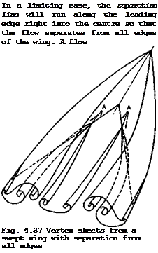
pattern which has been observed by R L Maltby (1962, unpublished) and which involves only vortex sheets is sketched in Fig. 4.37. It is complicated by
the fact that the attachment lines (A) on the wing, which divide the air which is drawn into the rolled-up cores of the vortex sheets issuing from the lea edges from the air which is not and which flows predominantly rearwards, must intersect the trailing edges. Different flow directions on either side of the intersection points then out and split up the vortex sheet from the trailing edge, and the free edges thus generated roll up into new cores. This type of flow is far beyond any available means for calculating it; it is also undesirable in practical applications since forces and moments on such a wing (and on a tailplane behind it) are liable to change with attitude in a drastic and uncontrollable manner.


