Special Problems in Hover
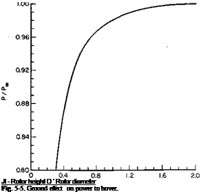
Ground Effect. The effect of ground proximity on the hovering rotor is to reduce the induced power required to deliver a given thrust. Essentially, the ground plane creates an image rotor that induces an upward velocity, which in turn reduces the induced angle of attack so that the lift vector of each section is tilted more nearly vertical. A theoretical analysis of ground effect can be found in Ref. 6.
Although the ground effect is on the induced power only, it is common practice to account for it with a correction factor to the total power. This factor, which is the ratio of power required to hover IGE (in-ground effect) to that required to hover OGE, is a function of the ratio of the height of the rotor above the ground to the rotor diameter. It would be expected to hold only as long as the induced power required to hover is approximately the same proportion of the total power in the test data from which the factor was obtained; for example, the power required to hover IGE divided by the power required for OGE should be less for the more heavily loaded rotors of VTOL aircraft than for a helicopter rotor. Figure 5-5 is a graph which shows the ratio of power required to hover IGE to that required to hover OGE for the average helicopter. This curve was obtained as the best fit to considerable amounts of test data on both single and tandem rotor helicopters.
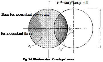
Rotor Interference. A problem peculiar to the multirotor helicopter is that of rotor interference. Reference 7 presents a theoretical treatment of the effect of rotor overlap on the induced power which compares favorably with test data. The following is an approach to the problem which agrees closely with results of Ref. 7.
Consider two overlapped rotors as shown in Fig. 5-6.
Let T equal the thrust of both rotors; ut equals an “average’ induced velocity.
If the profile power Pp is assumed to be independent of the overlap for a given thrust, then, for a constant induced power, the thrust must vary inversely as the induced velocity, for P, = Tvt. Thus
l = s,
T0 v
 |
where a sub 0 refers to zero overlap.
Now
1/3
Similarly, for a constant thrust the ratio of the induced powers with and without overlap is
(РЛ _ (M112.
Pio/constant thrust AJ
If the overlap is defined as 1 — d/D, the angle shown on Fig. 5-6 is given
by
у = cos-1 (1 — overlap) and from the geometry of the figure
A у — sin у cos у
 |
|
A0 %
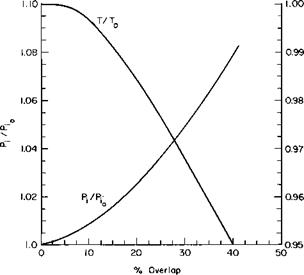
These relations are presented graphically in Fig. 5-7 as a function of the overlap.
Fuselage Download. The thrust that a rotor must develop in hover is actually greater than the gross weight of the helicopter, because the down – wash from the rotor (or rotors) produces a vertical drag on the fuselage in
the downward direction. This additional download can be calculated approximately as the product of the disk loading (dynamic pressure in ultimate wake) and an equivalent flat plate area,/„, of the fuselage planform area in the rotor slipstream:
T
download = — /„.
il
Thus
T=w + jL (5-13)
or
T w
~ 1 – ША)
From this equation it can be seen that the gross weight of the helicopter should be increased by the factor [1 – (fJA) ~1 in order to calculate the
|
Fig. 5-7. Effect of overlap. |
power required by the rotors in hover. This factor increases the thrust by approximately 1% for single-rotor helicopters to 3% for multirotor configurations, numbers which can vary considerably, however, depending on the specific distribution and shape of fuselage area beneath the rotor.


