The general (series) distribution of lift
In the previous section attention was directed to distributions of circulation (or lift) along the span in which the load is assumed to fall symmetrically about the centre-line according to a particular family of load distributions. For steady symmetric manoeuvres this is quite satisfactory and the previous distribution formula may be arranged to suit certain cases. Its use, however, is strictly limited and it is necessary to seek further for an expression that will satisfy every possible combination of wing design parameter and flight manoeuvre. For example, it has so far been assumed that the wing was an isolated lifting surface that in straight steady flight had a load distribution rising steadily from zero at the tips to a maximum at mid-span (Fig. 5.31a). The general wing, however, will have a fuselage located in the centre sections that will modify the loading in that region (Fig. 5.31b), and engine nacelles or other excrescences may deform the remainder of the curve locally.
The load distributions on both the isolated wing and the general aeroplane wing will be considerably changed in anti-symmetric flight. In rolling, for instance, the upgoing wing suffers a large decrease in lift, which may become negative at some incidences (Fig. 5.31c). With ailerons in operation the curve of spanwise loading for a wing is no longer smooth and symmetrical but can be rugged and distorted in shape (Fig. 5.3Id).
It is clearly necessary to find an expression that will accommodate all these various possibilities. From previous work the formula / = pVT for any section of span is familiar. Writing / in the form of the non-dimensional lift coefficient and equating to pVT:
![]()
(5.44)
 |
|
is easily obtained. This shows that for a given steady flight state the circulation at any section can be represented by the product of the forward velocity and the local chord.
Now in addition the local chord can be expressed as a fraction of the semi-span s, and with this fraction absorbed in a new number and the numeral 4 introduced for later convenience, Г becomes:
Г = 4Crj
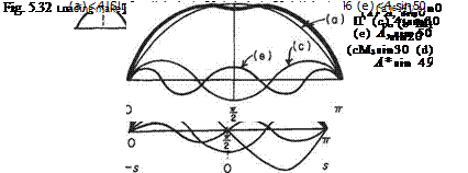
where Cr is dimensionless circulation which will vary similarly to Г across the span. In other words, Cr is the shape parameter or variation of the Г curve and being dimensionless it can be expressed as the Fourier sine series sin пв in which the coefficients A„ represent the amplitudes, and the sum of the successive harmonics describes the shape. The sine series was chosen to satisfy the end conditions of the curve reducing to zero at the tips where у = ±s. These correspond to the values of 9 = 0 and 7Г. It is well understood that such a series is unlimited in angular measure but the portions beyond 0 and 7Г can be disregarded here. Further, the series can fit any shape of curve but, in general, for rapidly changing distributions as shown by a rugged curve, for example, many harmonics are required to produce a sum that is a good representation.
|
‘•ЧУЛУ* |
 |
In particular the series is simplified for the symmetrical loading case when the even terms disappear (Fig. 5.32 (II)). For the symmetrical case a maximum or minimum must appear at the mid-section. This is only possible for sines of odd values of 7t/2. That is, the symmetrical loading must be the sum of symmetrical harmonics. Odd
harmonics are symmetrical. Even harmonics, on the other hand, return to zero again at 7t/2 where in addition there is always a change in sign. For any asymmetry in the loading one or more even harmonics are necessary.
With the number and magnitude of harmonics effectively giving all possibilities the general spanwise loading can be expressed as
![]() (5.45)
(5.45)
It should be noted that since / = pVT the spanwise lift distribution can be expressed as
![]() (5.46)
(5.46)
The aerodynamic characteristics for symmetrical general loading are derived in the next subsection. The case of asymmetrical loading is not included. However, it may be dealt with in a very similar manner, and in this way expressions derived for such quantities as rolling and yawing moment.


