CHARACTERISTICS OF CANARD CONFIGURATIONS
The basic equations of longitudinal balance and stability suggest that “any” type of combination of two “wings” may be used in designing an airplane. One unconventional arrangement is the canard type configuration, flying tail- first, so-to-speak.
Canard Principles. Many pages of this and of the next chapter, are devoted to the description of all the interaction and interference effects to which a horizontal tail surface are subjected. From time to time, the possibility has, therefore, been investigated of placing the “stabilizer” ahead of the wing, where “no” disturbance may have to be expected. Another argument in favor of this arrangement is the fact that the canard surface will reach its maximum, lift at a lesser airplane angle of attack (and/or wing lift-coefficient) than a tail surface (located in the wing’s downwash). It has been stated accordingly, that the wing of the canard-type airplane would be stall-safe. While this can certainly be true, stalling of the canard surface must be expected to have consequences. As the history of airplane design demonstrates, therefore, canard configurations have only been built and tried (23,a, b) for experimental purposes. There are specific applications, however, particularly in winged missiles, where operation at higher lift coefficients may not be required. There can also be other inducements in the areas of drag and arrangement VTOL types (23,f) in favor of a canard system, such as in large supersonic airplanes (24), for example.
Across the Span. The magnitude of downwash is primarily considered in or near the plane of symmetry. The distribution across the wing span depends on the lift coefficient. In rectangular wings, downwash increases slightly on either side of the plane of symmetry. In tapered plan forms, it decreases on the other hand; and it does so to a considerable degree in highly tapered wings such as that in figure 30. As a consequence, the stabilizing effectiveness of the horizontal tail, is a function of its lateral location. Results when using a pair of surfaces attached to the nacelles, as in part (B) of the illustration, are as follows:
|
tail configuration |
dCL |
do£w /doc |
de/doc |
|
pair of delta tails |
0.13 |
0.4 |
– 0.6 |
|
outboard pair of tails |
0.10 |
0.6 |
– 0.4 |
|
estimated for inboard |
pair 0.03 |
0.2 |
– 0.8 |
In short, the inboard panels are very inefficient by comparison, on account of a high downwash ratio.
(23) Characteristics of canard-type airplanes:
a) Focke-Wulf “Ente”, see NACA Rpts AC59 (1927) & 132 (1931).
b) Hubner, Focke-Wulf F-19 “Ente”, ZFM 1933 p 223.
c) Kiel, Stability of “Ente” Airplanes, NACA TM 612 (1931).
d) Flying Model of Curtiss P-55, tested in Full-Scale Tunnel, NACA W Rpts L-627, 630, 650 (1943/45).
e) Sandahl, Body Wing Canard, NACA TN 1295 (1947).
f) Borst, High Speed VTOL Aircraft Aerospace Eng. Aug 1962
(24) Hibbard, Supersonic Transport Airplanes (Aero Space Engg, July 1959 p 32) with V 1500 kts, are proposed with Canard Control. Drag penalty associated with trim at M = 3 is so great, that canard configuration is selected.
|
J, =0.5ljy = (0.5+i/(*)Uel |
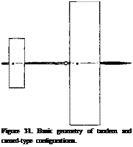
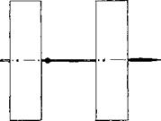
Tandem Configuration. We will first consider the tandem system as in part (a) of figure 31. The separation distance between the two wings may be I = b. The upwash at the place of the forward wing is assumed to be zero, while the down wash at the second wing may correspond to dz/doC = — 0.5. Using equation (2) balance requires
Cm,=CLl (S, /S)(Щ) = |Cm2J
= CL2 (S2/S)(|^/i|) (34)
where S = S, + S2, and і = lt + {$2) = separation distance = reference length. In terms of the angle of attack
(dCL / do: )oc (S f /S)( і, /І) = (dC L /do:) (осц +i)(S2/S)|^/
(35)
where <Хц = (1 — 0.5) ос, and і = angle at which the second wing is set against the first one. One and the same slope dCL /doc shall be assumed to apply to either wing (when flying alone). Therefore:
ocS, i, =(0.5 a +i)SeUz) (36)
where the absolute value is used for the агпъ?2 . In a tandem system (where S( = S2 = 0.5 S):
ос Лх = (0.5 ос + i/oOI-41 і or -4 = + l!°c) 1
(37)
where the 0.5 reflects the influence of the downwash.
Stability. Using next equation (5) static stability requires that
I dC^/dof I ^dC^/dct’
0.5(dCL /da: )(S2 /S) I / Д |>(dC L /doc )(S, /S)(І Ц)
(38)
Note that Jt is considered to be positive, and £ to be negative. For neutral stability, thus:
0.5SU | = S,^
(39)
and in a tandem system (where 82=8, = 0.5 S)
0.25li2l = 0.5^; or і,=0.5|ігІ (40)
In fact, to be stable, must be somewhat shorter than 0.5 Jz. Introducing now the maximum permissible J{ into equation (37)
we correctly obtain і = 0. We will now specify a stability corresponding to dCm/dCL = (dC^/da: )(da: /dC L), for example = — 0.01, which means a stabilized length of д хЦ = 1% of the separation distance For an assumed dCL jdoC = 0.06, we then obtain
dCfJdoC = – 0.06 (д хЦ) = dC^H/doC + dC^JdoC
= 0.06 (0.5) (JJJ)- 0.5 (0.06) 0.51 Je IЛ I
= 0.03 — 0.015 І і / J I
Since I JzI = J-J, , we obtain
dCm/doC° = 0.03 Ц /I) – 0.015 (1 – і, /І) – 0.06 (д хЦ)
and the moment arm of the first wing:
£il£ = (1/3) — (4/3) A xjj (42)
For neutral stability (kx/J = zero), this equation correctly yields =1/3.
Control. Combining equations (37) and (42)
Jji = (0.5 + i/oc) J£ll = (1/3) – (Ф)(АхЦ) (43)
|
|
|
A) TANDEM CONFIGURATION d = – 0.5 cid |
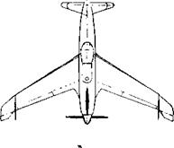
B) CANARD-TYPE d = ZERO Sc = 0.2 S
After replacing again, we eventually obtain the approximation
i/oc = – 6(д x/J) + 8(д xUfsz – 6 (д x//> (44)
Thus, the tandem system considered can be expected to be stable when and if the CG is ahead of the 1/3 point of the separation distance. The configuration can be controlled or trimmed by reducing the angle of attack of the rear wing, roughly at the ratio of ді/д ос = – 6% for each stabilized percent of the separation distance.
Canard Analysis. Assume that the forward wing reduces in area, say to 25% the rear wing, or to 20% of the combined area. In a xough analysis, we may assume no interference between the two “wings” (no downwash). The neutral location of the CG is then found to be at
i, = li2KS/S ) = 510,1 = (5/6)^ (45)
where Sc = area of the canard surface. To be stable, the CG must be placed 1% of the reference length ahead of the neutral point, for each increment equal to 0.01, of the stability derivative dCryydCL. This is as in conventional airplane configurations, but only when the wing is not affected by downwash or upwash, respectively of the smaller, stabilizing surface (located either ahead or aft).
dC^dc* = +0.015 FUSELAGE
= +0.048 F + CANASD = -0.037 F + WING dCL/dc£ = 0.070 WING + F
|
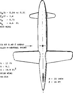
Figure 32. Large-scale canard model as tested in the Propeller – Research Tunnel (23,e). Rc = 1.5(10)*. |
Basic Configuration. The large-scale model of a canard configuration is shown in figure 32, consisting of a plain body of revolution, a straight wing in high position, and a stabilizing surface mounted mid-wing near the nose of the fuselage. Pressure-distribution tests indicate that the load distributions across the span, both of the wing and canard surface, display considerable dents in the center. The one in the wing, seems to be responsible for an induced drag at least 10% higher than expected. The effectiveness of the canard surface can be understood when assuming that the part of the fuselage “covered”, only produced 1/2 of the lift as it would, without the fuselage present.
Canard Effectiveness. Investigation of the canard surface of light weight Curtiss P-55, figure 33 airplane in the NACA’s Full-Scale Tunnel (23,d) reveals:
(a) When rotating the canard surface against the fuselage, its force varies corresponding to dC ^ /di = 0.042.
(b) When rotating the surface together with the fuselage, the differential corresponds to dC ^н/dor = 0.057.
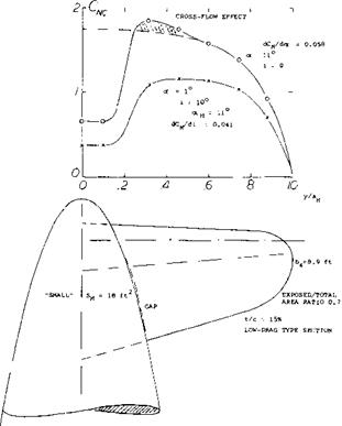
The load distribution, plotted in figure 34, shows a deep dent or gap in the center of the canard-surface span. The pressure distribution induced upon the fuselage, does not fill up the gap. Evidently, there is not much body left ahead of the leading edge, where a cross flow could develop. In fact, the gap is so big that we may consider 15% of the canard surface to be cut out and to be ineffective. Using the function explained in the Chapter III the “lift angle” may thus be expected to be
dar/dCLH = (10.5 + 19/AH )/0.85 =
14.9/0.85= 17.4° (46)
where Au = 4.4, including the part covered by the fuselage. The result as under (b) above is 1/0.057 = 17.6°. Note that we did not reduce the effective aspect ratio since the boundary layer and/or wake at the nose of the fuselage are very small. Note also that area and aspect ratio and lift curve slope of the canard surface used in the following tests, are larger than those of the surface used in figure 34.
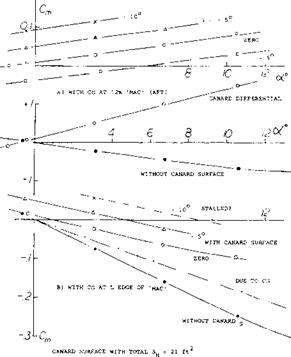
Stability Contributions. The pitching moment characteristics of the P-55, as tested with the CG located at 12% of the “mac” (id est, behind its leading “edge”) are plotted in part (a) of figure 33. Without the stabilizer, the configuration is stable, dCm/doc = – 0.0063 or dC„,/dCL = – 0.0063/0.07 = – 0.09, where 0.07 = dCL/doc as tested. To balance this moment at a certain lift coefficient the canard surface has to provide a positive (destabilizing) moment. Stabilization in any canard configuration can thus only be obtained from the wing and that contribution is not adequate in the condition as tested, with the CG at 12% “mac”. Positive stability can be obtained, for
example, by moving the CG forward to the leading edge of the “mac”. Part (b) of the illustration shows the corresponding pitching moment characteristics. To trim the airplane, say to CL = 0.5 where oc = 7 , a stabilizer angle і of at least + 7 is required. The aerodynamic angle is then осц = оГ+і = 7 + 7=14, and the lift or normal-force coefficient of the canard surface is between 0.8 and 0.9. In other words, this coefficient grows faster than that of the wing.
|
w = |
8000 |
lb |
EXPERIMENTAL: 4000 lb |
|
|
b = |
41 |
ft |
S = |
210 ft |
|
c = |
5.6 |
ft |
SH = |
10% S, ‘LARGE" CANARD |
|
A = |
8 |
– |
Sy = |
13% S, IN 3 FINS |
|
t/c = |
15 |
% |
CLx = |
1.1 WITHOUT FLAPS |
|
dCL/dcx = 0, |
.07 |
CDmin |
0.021 |
|
28° ANGLE OF SWEEP ALL MOVABLE CANARD SURFACE = 3(10)6 |
|
! f
|
|
Figure 33. Longitudinal characteristics of Curtiss P-55 airplane, as tested (23,b) in the Full-Scale Tunnel. Data of full-scale craft listed. |
|
Figure 34. Lift or load distribution of the “small” (23,b) canard surface of the Airplane as in figure 33. P-55. |
Stalling of the canard surface takes place at oC ^15°, where Сиц ~ 1.0. Stability is still preserved at the corresponding lift coefficient of the wing (CL ^ 0.6). In fact, stability increases on account of stalling. It is completely impossible, however, to trim the airplane above this limiting coefficient. Since negative lift in the canard surface will “never” be of any practical interest, the airfoil section used should preferably be cambered, thus providing higher maximum lift. To avoid sudden stalling (which might prove to be “fatal” for the airplane) the section shape should be such that stalling starts gently (from the trailing edge). One way of extending the range of effectiveness of the canard surface, is to make its surface larger. Roughly, to double the maximum lift coefficient at which the P-55 could be flown (from CL = 0.6 to 1.2) it would be necessary to double the size of the stabilizer area (from 10% to 20% of the wing area).
Aspect Ratio. It is basically desirable that the canard foil produces comparatively large positive lift-forces — with a lift-curve slope as low as practicable. Therefore, the canard surface should have a small aspect ratio. For example, the “larger” surface (S H = 10% S) used in the configuration in figure 33, has a geometrical A = 6.8. Upon reducing this ratio, say to 1/3, its lift curve slope can be expected to be reduced to 70%. As a consequence, stability would be increased by Д (dC^dC^) = – 0.06. After relocating the CG, accordingly, control (trim) might then be obtained up to CL ~ 0.8 (instead of 0.5 as with the large-aspect-ratio canard surface).
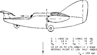
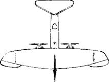 THE LARGE FIN, FOUND NOT TO BE SUFFICIENT, WAS AUGMENTED BY A PAIR OF AUXILIARY FINS MOUNTED BELOW THE WING, NEAR THE TIPS.
Figure 35. Focke-Wulf F-19 “Ente” research airplane, built and flight-tested (23,a, b) between 1927 and in 1936.
Full Scale Experience. One of the few canard-type airplanes built and flight-tested is the Focke-Wulf “Ente” (first 1927, and then 1936), shown in figure 35. Reports by its designer and the principal research pilot (23,a, b) reveal practical results as follows:
A) Advantages:
(a) It is true that the wing of a canard-type airplane cannot be stalled.
(b) The canard type does not have any slipstream interference.
(c) Lateral (aileron) control is fully available, at all times.
(d) Even when and if the airplane could be controlled to angles of attack above stalling (as tested to (X = 45 , in a wind tunnel) spinning is “safe”; the CG located “ahead” of the wing prevents flat spins.
(e) The configuration lends itself to the use of a nose – wheel tricycle landing gear.
B) Disadvantages:
(a) When the canard surface stalls, the airplane recovers by way of a certain dive. This is dangerous when it happens near the ground and in particular during the landing approach.
(b) The fuselage (extending far forward) is destabilizing about the vertical or normal axis. As a consequence, unusually large vertical “tail” surfaces are required.
(c) Longitudinal control is sluggish by comparison, particularly during take-off where the slipstream does not help.
(d) In regard to speed performance, the canard configuration is said to be potentially inefficient.
In view of the positive load to be carried by the canard surface, the 1936 “Ente” had an area ratio S^/S= 17%, a well-cambered section, set at an angle of і = + 10 , and it is equipped with full-span trailing-edge flaps, used as elevators. At a usual CG position 26% “mac” ahead of the wing’s hedge, the stability corresponds to dC^JdC^ = — 0.10. When taking off at C L = 1.2 (total on wing surface), the lift coefficient in the canard surface must have been CLH between 1 and 2.
High-Speed Configurations. While the canard configuration does not seem to be profitable when used in otherwise conventional airplanes, there may be other applications where stabilization by means of a surface ahead of the wing will be desirable:
(a) in winged and guided missiles, where higher lift coefficients (as in airplanes when landing) may not be required.
(b) in supersonic and low-aspect ratio airplanes, where the canard arrangement is said to present less drag.
(c) in configurations where the engines and their weight are located aft, a comparatively long portion of the fuselage is ahead of the wing. The fuselage can, therefore, conveniently be utilized as a “boom” supporting the horizontal control surface.
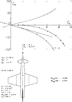
Supersonic Airplane. Figure 36 presents the pitching moments of a straight-wing configuration, tested at M = 0.7. As explained elsewhere, lifting and longitudinal characteristics at this M’number, are essentially or qualitatively as in incompressible fluid flow. From figure 36 it is noted that:
(a) Because of the low aspect ratios of 3.0 and 3.1, the CL(oc) functions of wing and control surface are slightly non-linear.
(b) The wing pitching moment non-linearity is increased by the swept-back position of the sharp lateral edges, in reference to the CG.
(c) After including a certain non-linear component due to the fuselage, the C^Cl.) function of wing plus fuselage, is distinctly non-linear. This is to say, the value of the negative grows with Cu at an increasing rate.
(d) After adding the positive moment due to the canard surface, stability is reduced to zero at near zero, for a position of the CG at 3% of the “mac”. The pitching moment coefficient increases roughly as Cm== -.0.2 CL2.
(e) The canard foil stalls at ос ц =10°, where its lift coefficient is somewhat above 0.5 and the moment contribution CmH between 0.07 and 0.08.
To Improve the longitudinal characteristics, the non – linearities characteristics of the wing (not the canard surface) should be eliminated, the maximum lift of the canard surface should be increased and its lift-curve slope be reduced. Steps as follows would be suitable:
1) reduce the canard A’ratio, and increase its area at the same time,
2) increase the canard moment arm, thus assisting area,
3) reduce sweepback (making leading edge straight),
4) reduce the fuselage diameter, if possible.
|
Figure 36. Pitching moment characteristics of a high-speed airplane configuration, with canard control (25,a). |
(25) Characteristics of high-speed canard designs:
a) Peterson, With Straight-Wing, NACA RM A57K27.
b) Boyd, Delta Configurations, RM A57J15 and A57K14.
c) Peterson, Delta at High Speeds, RM A57K26.
d) For comparison see same wing-body combinations as in (a),(b),(c), with horizontal tail aft in (19).
|
M = 0.7? Rc = 4(10 )6
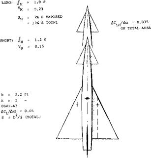
Figure 37. Longitudinal characteristics of a high-speed delta-wing canard configuration, tested (25,b) at M = 0.7, with two different lengths of fuselage and canard moment arm. |
Fuselage Length. Comparative tests on the delta-wing configuration as in figure 37, show the influence of the length of fuselage and canard moment arm:
(a) The lift in the exposed panels of the canard surface is independent of fuselage length; ДС^/Ло^ = 0.063, based on exposed area (equal to 6.9% of that of the wing).
(b) The canard moment arms arejl4 = 1.2 c for the short, and 1.8 c for the long fuselage; the ratio is ~1.5. By comparison, the moment differentials due to the surface correspond to a ratio of 1.8.
(c) The longer fuselage causes an increment A(dCm/dCL) between -1 0.03 and + 0.04.
(d) The canard surface stalls at an angle of attack (oc + i) ~ 25°, where its lift or normal-force coefficient is in the order of 1.4. The corresponding maximum canard contribution is analytically:
Сти = + 1*4 (0.069) 1.2 ~ + 0.12 for the short fuselage
= + 1.4 (0.069) 1.8 ~ + 0.18 for the long fuselage
As discussed in the next paragraph, the “long” moment is even larger than this. The longer fuselage thus permits either to trim to at least 1.5 times the wing lift coefficient, or to compensate for at least 1.5 times in terms of ^(dC^/dCL) of the configuration.
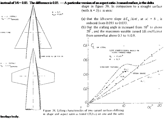 Interference. The canard surface leaves behind a certain downwash — and a pair of tip vortices. The possible interference of this system with the wing is mentioned in several reports (25). In the case where the canard surface is large the downwash is highly destabilizing. However if the distance is large and the front surface small the consequences of such interference are of minor importance. Theory predicts that the two lifting surfaces have the same induced characteristics as a wing to whose load distribution the lift of the canard surface is added. In reality, the wing load is expected to be reduced in the center, and to be increased outside the canard span. Again, this may not be important in a small straight wing. However, in the example of a delta wing as in figure 37, a relocation of lift from the center outboard, can be expected to make the wing’s pitching moment more negative (nose-down and stabilizing). There is some indication of possible interference in (b) above, where the canard moment grows to “1.8”, while the moment arm ratio is only 1.5. It can be speculated that the short-fuselage design exhibits a differential due to interference in the order of &(dCm/dCL) = – 0.02. This differential can readily be explained, as above. The fact that the long configuration does not experience a similar differential, may be associated with the much longer distance that the downwash field has to proceed, before it reaches the wing. It. is also likely that the canard downwash reduces the positive moment of the fuselage. Finally, de/doc at the location of the wing, must be expected to reduce, as the angle of attack is increased.
Delta Canard While above, the moment arm of the canard surface is found to be of value in postponing stalling, the fact remains that this surface always contributes a destabilizing moment. Using equations (38) and (44), the location of the neutral point behind the canard surface is found to be
– (S/Sc)/(1 + S/Sc)(dC L /doC )/(dC L /dot) (47)
Stability can thus be increased by reducing the lift-curve slope of the canard, in comparison to that of the wing. In view of
doc /dCL w 11 + 20/A
(Chapter III) this can be done by reducing the aspect ratio of the canard surface. When, for example, a wing with A = 6 is combined with a canard surface having Aw =6, equation (44) indicates IjJ = 5/6. Reducing Ац , say to 2, we obtain the ratio
(dCL/doO/(dCL/doc)„ =
(doc/dCL )й /(doc/dCL ) – 1.5 and a neutral point at
Jjf = 7.5/8.5 = 0.88


