Circular Arc Airfoil
The center of the circle is chosen on the imaginary axis in the f plane fi = im and from Eq. (6.27) a = Cl4 sec /3 and m = a sin /3. This results in the circulai arc airfoil shown in Fig. 6.14a with chord с = C. Note that since the circlf passes through both critical points A and D, the corresponding points on thjf airfoil are sharp. Also, points B[f = i(a + m)] and E[f = — i(a – m)] on th{! circle, at the top and bottom, both transform to the same point on the аігіоЦ Y = 2im. The schematic streamline pattern for the flow in both the physical and circle planes is shown in Fig. 6.146. Note that the forward stagnation point on the circle occurs when 0 = я + 2a + /3 and therefore the forward stagnatio| point on the circular arc can be found from the transformation. The velocity 4 the trailing edge is given by Eq. (6.32) as
The zero lift angle is seen to be equal to -/3. The maximum camber ratiq
defined as the ratio of the maximum ordinate 2m to the chord c and is tan|
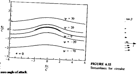
An interesting special case occurs when the circular arc is set at an
of attack of zero. From above, it appears that the forward stagnation poin
 |
circular arc airfoil’XeT(Tan angle^f’Xck)deSCriPti0n °f S, reamlines in the circle and the
FIGURE 6.16
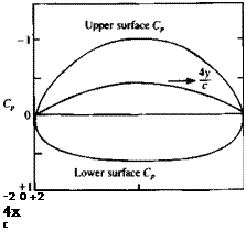
 Pressure coefficient for circular arc at zero angle of attack.
at the leading edge but since a critical point exists there, L’Hospital’s Rule must be used again and with / = – cl4 and в = n + /3, the complex velocity at the leading edge is
w(y == Qao cos2 Ре~ър (6.55)
This is equal in magnitude to the velocity at the trailing edge and the flow is seen to be symmetric with respect to the z axis. This is an example of a lifting flow with no stagnation points (see the streamline pattern in Fig. 6.15) and with a flow path of equal length for particles traveling along the upper and lower surfaces. The pressure coefficient is plotted in Fig. 6. 6.


