Distributed Singularity (Panel) Numerical Methods
Thin-airfoil theory is convenient and satisfactorily accurate; however, it has several limitations. It cannot be applied to arbitrarily thick airfoils with confidence because thickness effects were ignored in the derivation of the theory. If pressure-distribution information is required in addition to the airfoil lift and moment, then more of the coefficients in the Fourier-series representation must be found. Also, the result is Ap across the mean camber line and not the pressure distribution on the surface of the airfoil, as needed for a related boundary-layer solution.
The advent of digital computers offers the attractive alternative of a numerical rather than an analytical solution, and many of the assumptions required for the analytical solution can be dropped. In this section, we introduce one of these numerical approaches. It relies on superposition of singularities much like the analytical method; however, instead of a Fourier-series representation for the continuous variation of camber-surface vorticity, we seek a piecewise variation of the vorticity on discrete segments of the airfoil surface. Because the three-dimensional extension of one of these segments is a rectilinear “panel” on a wing surface, these methods are known as panel methods.
Panel methods are not restricted to the use of a vortex singularity to represent an airfoil or wing. Source and doublet singularities, discussed in Section 5.4, also may be used. At times, singularities are used in panel methods in combination. For example, it may be useful to represent an airfoil by a source distribution along the mean camber line to simulate the thickness effects plus a vortex distribution along the airfoil surface to account for the generated vorticity and lift.
There are a variety of panel methods. This introduction is intended to provide an idea of how the method is set up and how the aerodynamic performance of an aerodynamic surface is attained. The method outlined is not a so-called finite – difference or CFD scheme. Rather, panel methods use the power of a computer to solve large sets of simultaneous algebraic equations that are generated by repeated application of the tangency-boundary condition. Panel methods of solution are extended to three-dimensional wings and discussed in detail in Chapter 6. Eppler, 1990 is a benchmark presentation of panel methods, and several chapters of Applied Computational Aerodynamics, referenced in Chapter 6, present a good review of airfoil-panel methods.
The steps in any panel method of solution are the following:
1. Choosing the number and type of singularities. These singularities have an unknown strength associated with each one. For example, if there are N singularities, there are N unknown strengths. For this, we need N equations.
2. Discretizing the aerodynamics surface into N segments or panels. This simply means figuring out where on the surface we will place the singularities (Fig. 5.27). It is important that panels need not be all of the same size. They should be concentrated in regions where the variables are expected to undergo rapid changes. This most often happens in regions of rapid geometry change. Thus, for example, we should expect to see singularities clustered (i. e., small panels) near the leading edge of an airfoil where the curvature is greatest and near the trailing edge because that also is a region where there is a rapid change in flow properties.
3. Placing the control points. To devise N equations, recall that the singularities are solutions of the Laplace’s Equation. In solving a differential equation, we must generate the generic solution and then impose the boundary conditions for the specific problem. Note that when we make use of the flow singularities, we already have the generic solution. The panel-solution method is based on satisfying the surface-tangency boundary condition. Because there are N unknowns, we must satisfy the surface-tangency condition at N points on the surface. These are called the control points, and placement follows logic similar to the placement of the singularities.
4. Writing one equation for each control point. Here, the influence of all of the singularities and the freestream at a fixed control point is summed. Then, it is required that the net local velocity be tangent to the surface at that control point or, equivalently, that the normal component of velocity at the control point be zero. To accomplish this, the relative position of the control point relative to the location of all of the singularities is required, as well as the geometrical slope of the surface. In addition, it must be decided how the singularities are to be distributed on their respective panels. In the simple concentrated vortex model illustrated herein, the continuous vortex sheet along the panel is combined into a single point.
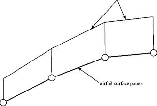
So-called higher-order vortex panel methods may use a curved panel. These methods also represent the vorticity as a linear or nonlinear variation along each panel. In general, higher-order panel methods achieve greater accuracy than using combined singularities on flat panels—but at the expense of a more complicated formulation and, often, with additional computation time required. The Program AIRFOIL (see subsequent description) provided for use with this textbook uses flat panels with a linear variation of vorticity from one end of the panel to the other.
5. Imposing the Kutta condition (if necessary). Lifting sharp-edge airfoils requires the Kutta condition to produce a realistic solution; other geometries, such as ellipses and cylinders, do not. Requiring that the velocity directions at the trailing edge are the same on the upper and lower surfaces at a cusped trailing edge, or that at a finite-angle trailing edge there must be a stagnation point, imposes the Kutta condition. This condition replaces one of the equations in Step 4, thereby reducing the required number of control points by one.
6. Solving the system of equations generated by Steps 4 and 5. Solving for N unknown singularity strengths requires the solution of a full Nx N matrix. Clearly, the more panels that are used (i. e., the larger the value of N), the more accurately the method represents the continuous vorticity distribution along a continuous airfoil surface. Thus, the limitation on the panel method is how quickly we can solve such a system. As computational resources improve in processing speed, the number of panels used also can increase. For example, older PCs running at 33 MHz can solve a system with N = 41 in about 2 minutes. Far larger values of N can be handled on modern desktop computer systems.
We next demonstrate an application of the panel method, first by a simple example and then by using a computer code supplied with the text. Consider the NACA 0012 airfoil shown in Fig. 5.27, where the circles in the figure indicate the locations of the combined vortices (N = 41 unknowns) on the airfoil. The vortices define the end point of the panels and the control points are located midway between the ends of the 40 panels. Note the clustering of vortices (i. e., small panels) near the leading and trailing edges of the airfoil. Also note that there is one vortex at the leading edge and two coincident vortices at the trailing edge.
Because the airfoil shape is known, the coordinates of the control points can be generated approximately by a simple averaging of the coordinates of the vortices on either side. A slightly more accurate procedure is to average the x/c coordinate and then use the equation for the airfoil surface to generate the z/c coordinate of the control point. In either case, the result is the known positions of 40 control points, which are used to generate 40 equations. The remaining equation results from the Kutta condition.
|
(a) |
|
clustered vortices
Figure 5.27. NACA 0012 airfoil with 41 vortices indicated. |
 |
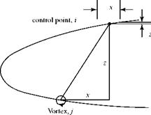
Next, we impose the tangential-velocity boundary condition at the 40 control points. To see how this is done, consider the velocity induced by one vortex at one control point, as shown in Fig. 5.28. Also shown is the panel on which the control point is located. The coordinates of the end points of the panels (i. e., the nearest vortices on either side of the control points) are used to determine the unit tangent to the panel. The coordinates of the control point are midway between the end points of the panel, called the control point (xi, zi). The coordinates of the clustered vortex are (xj, zj). Recall from Chapter 4 that the velocity components induced by a vortex at a distance r from the vortex are:
Г z Г x
2n (x2 + z2) 2n (x2 + z2)
where Г is the strength of the vortex and x and z are the distances in the coordinate directions from the center of the vortex to the control point. Now, the unit normal to the surface is given by:
„ – Azii + Axik n = . 1 = .
VAxf + Az2
Thus, the component of velocity normal to the surface at the control point, i, induced by the vortex element, j, is:
where Tj is an as-yet-unknown vortex strength and:
x = xi – xj, z = zi – zj.
An equation including all of the unknown vortex strengths is obtained by summing the contributions to the normal velocity at control point i from (a) all 41 vortices, and (b) the normal component from the freestream velocity (with the body angle of attack accounted for, if necessary). The sum is then set equal to zero to satisfy the tangency boundary condition at control point i. Thus,
 |
|
There are 40 such control points at which this relationship must hold. Thus, simplifying and applying the expression at all of the control points requires that the system of 40 equations,
must be satisfied. Because there are only 40 control points and there are 41 unknown values of the vorticity, a closure equation is required. This is provided by the Kutta condition, which requires that the trailing edge be a stagnation point. Hence, the two vortices, which are coincident at the trailing edge, must have equal and opposite strengths and the equation for the Kutta condition is:
Гі + Г41 = 0. (5.38)
The set consisting of Eqs. 5.37 and 5.38 then can be solved for the 41 unknowns. However, a difficulty is introduced by Eq. 5.38, which states that the strengths of the two vortices at the trailing edge self-cancel. Hence, their influence at each of the 40 control points will self-cancel. In effect, two vortices have been removed from the system, leaving a set of 40 independent equations with 41 unknowns. This difficulty can be resolved by leaving a small opening at the airfoil trailing edge (i. e., the upper and lower surfaces do not actually meet). As a result, the two vortices can be distinguished from one another. This sends the two vortices back to contribute to the summations at the control points in Eq. 5.37 and returns Eq. 5.38 as the 41st equation. The problem then becomes well posed, a system of 41 equations in 41 unknowns. As a result, the formulas for airfoil-thickness distributions (e. g., the NACA four-digit series) used in the calculation often are modified so as to leave the trailing edge slightly open.
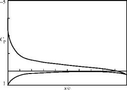
Eqs. 5.37 and 5.38 constitute a linear system. The right side of Eq. 5.37 consists of known quantities once the freestream velocity and angle of attack are specified. For the example given here, the values of the 41 vortex strengths are found by solving this linear system. When the vortex strengths are known, the magnitude of the induced tangential velocity at each control point due to all 41 vortices may be calculated. The pressure distribution at each control point on the airfoil surface then follows from the Bernoulli Equation, where the local velocity at the control point is the sum of the induced tangential velocity and the tangential component of the freestream velocity at that control point. Knowing the airfoil-surface-pressure distribution, the lift and moment coefficients follow and/or a boundary-layer solution can be used if a more accurate calculation is required.
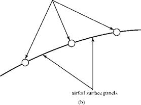
Note that although we used 41 vortices here, a much larger number must be used so that the predicted flow over the airfoil is smooth. To diminish this number, we may use the higher-order panel methods mentioned previously. Program AIRFOIL uses a linear variation in vortex strength over the panels, as shown in Fig. 5.29.
![]()
|
|
|
|
|
|
|
|
|
|
|
|
|
|

The panel method described here provides rapid and acceptably accurate pressure distributions for a given airfoil. The airfoil shape then can be modified, if necessary, to achieve a certain design or performance objective.
The main shortcoming of these methods is that the flows that are computed are necessarily inviscid and irrotational. Airfoils in a viscous flow but with little or no boundary-layer separation may be analyzed by patching together panel-method and boundary-layer solutions. Surface-pressure information from a panel method may be used in conjunction with viscous boundary-layer solutions to either estimate the skin friction on the airfoil or account for the flow-displacement effect due to the presence of the boundary layer interactively. This is illustrated in Chapter 8, where the frictional drag of a wing is evaluated by using an approach called strip theory (i. e., treat each section of the wing as two-dimensional). Many refinements
are possible in panel methods to increase the accuracy and/or decrease the required computational time. The student is referred to Althaus and Wortmann, 1981, and to the literature for a discussion of these improvements.
Restricting the flow to an irrotational, inviscid model is unrealistic at high airfoil angles of attack or even at low angles of attack for thicker airfoils or for high-lift multielement airfoils with flaps. In such cases, it becomes necessary to return to solving directly the governing partial-differential equations. Because these equations are nonlinear, superposition cannot be used. At the time of this writing, directly solving the nonlinear governing equations is still an evolving field (i. e., CFD). We introduce an important class of CFD methods—the finite-difference method—in Chapter 8 when flows with viscosity (which must be described by nonlinear equations) are considered.


