FLUTTER OF A TWO-DIMENSIONAL AIRFOIL
The example of the last section shows that for certain wing there exists an airspeed at which the wing response to a periodic forcing function tends to infinity at some particular frequency. At this combination of airspeed and frequency, the determinant of the coefficients of Eqs. 12 of § 6.9 vanishes and a nontrivial solution exists even when the forcing function vanishes: the aeroelastic system will oscillate harmonically without further excitation after an initial disturbance. The aeroelastic system is then said to be in the critical flutter condition.
In order to indicate the form of available aerodynamic tables and their application to flutter calculations, we shall consider in this section the critical flutter condition of a two-dimensional airfoil with an aileron and a control tab. Extensions to three-dimensional wings, tail surfaces, and other structures will be made in the next chapter.
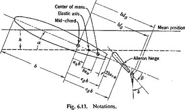
The Airfoil. Let us consider a two-dimensional airfoil of unit length in the spanwise direction, having four degrees of freedom h, a, /3, and 5, as shown schematically in Fig. 6.13, where
h = bending deflection of the elastic axis, positive downward, feet
a = pitching about the elastic axis, relative to the direction of flow, positive nose up, radians
/3 = angular deflection of aileron about aileron hinge, relative to wing chord, positive for aileron trailing edge down, radians
d = angular deflection of tab relative to aileron, positive trailing edge down, radians
We assume that h, a, /3, and <5 are infinitesimal, so that the flow remains potential and unseparated, and the linearization of the aerodynamic equations is justifiable.
|
|
The notations are shown in the figure. Note that the semichord is denoted by b. Other dimensions are referred nondimensionally to the semichord. Distances are measured with the mid-chord point as origin.
Thus,
cpb — distance between mid-chord and aileron hinge, positive if aileron hinge is aft of mid-chord
epb = distance between mid-chord and aileron leading edge, positive if aileron leading edge is aft of mid-chord
ahb = distance between elastic axis and mid-chord, positive if elastic axis is aft of mid-chord
Similarly, the dimensions dpb, fpb, xab, etc., can be identified.
Elastic Restraints. The displacements of the airfoil are restrained by elastic springs. A linear spring located at the elastic axis restrains the bending h. A torsional spring located at the same axis restrains the pitching a. The aileron rotation is restrained by a torsional spring at the aileron hinge line, and the tab by a spring at its own hinge. The spring constants will be denoted by Kh, Ka, Kp, and Ks. The elastic force due to a displacement h is — hKh, acting at the elastic axis, and in the direction opposing h. The moment about the elastic axis due to a is — a. Ka. Similarly, the moments about the aileron and tab hinges are — flKp and — 8Кб, respectively.
It is desirable to express the spring constants in terms of uncoupled natural frequencies as in § 6.8 (Eq. 6), and write
Kh = m/, Ka = /«соД Kfj = 1ршр K6 = Ком2 (1)
where m is the mass per unit span of the wing-aileron-tab combination, la is the moment of inertia per unit span of the wing-aileron-tab about the elastic axis, Ip is the aileron-tab moment of inertia about the aileron hinge, and К is the tab moment of inertia about the tab hinge. The frequencies coh, co„, cop, co<s are the uncoupled frequencies in radians per second, obtainable approximately by experiments, if necessary.
Structural Damping. The small structural damping of metal aircraft may be approximated by a force that opposes the motion and is in phase with the velocity. For simplicity of analysis, and also from lack of more accurate knowledge, we shall assume that the magnitude of the damping force is proportional to the elastic restoring force (cf. § 11.4). Since the motion of the airfoil is harmonic at the critical flutter condition, the condition is the same as in § 6.9, and the effect of the structural damping can be accounted for simply by replacing the terms hKh, a. Ka, etc., with terms hKh( 1 + igh), y. Ka( + iga), etc. The constants gh, ga, gp, gd are the damping coefficients.*
* Measurement by Fearnow on a full-scale airplane wing (C-46D) shows that g depends on the amplitude of motion and varies from 0.002 at an amplitude of vibration of 0.05 in. to approximately 0.012 at an amplitude of ± 5 in. (at wing tips). See Ref. ILL
Aerodynamic Forces.* The theory of oscillating airfoils, to be presented in Chapters 12 through 15, gives the necessary information about the aerodynamic forces acting on a fluttering wing. The theory is based on thin airfoils oscillating at infinitesimal amplitudes. At the flutter condition, we shall assume that
= ~ еш, a = а0еі(ш(+в‘), /3 = /30еІМ+Л), <5 = <50еі(ш(+в’) (2) where h0, a0, A)> йо are real numbers (small compared to 1), dv 62, 6S are the phase angles by which a, /3, <5 lead the wing bending displacement, and eo is the flutter frequency in radians per second. For a two-dimensional airfoil having these four degrees of freedom, in a flow of speed U, the aerodynamic forces are functions of the dimensionless numbers:
M = Mach number = U/c (3)
к = reduced frequency or Strouhal number = wb/U (4)
where c is the speed of sound propagation in the undisturbed flow. The aerodynamic expressions are simpler if the motion, as well as the forces and moments, are referred to the aerodynamic center. For a subsonic flow the aerodynamic center is located at the 1/t-chord point aft of the wing leading edge. Hence, let us introduce the following nondimensional generalized displacements:
(5)
* In most British papers, the so-called classical derivative theory is used. Following Frazer and Duncan, the aerodynamic forces are assumed to be linear functions of the generalized displacements, velocities, and accelerations. For example, let s denote the linear downward displacement of the leading edge and a the increase in angle of attack from a mean position at a local chordwise section of the wing. Then it is assumed that the corresponding local aerodynamic lift L (positive upward) and the moment M (referred to the leading edge, positive nose up), per unit span, may be expressed in the form
LI(pV2c) = (Іф + Іф + Іф)/с + (k a + lid + lx«)
-M/(pUV) = (тф + тф + тф)Іс + (гпф. + тф + тх а)
|
where с is the local chord and a superposed dot denotes differentiation with respect to a dimensionless time r = Ut/c. The coefficients 4, 4, etc., are assumed to be independent of the reduced frequency, aspect ratio, planform, and modes of motion of the wing. In an incompressible fluid, a set of “mean experimental values” given by J. Williams (Ref. 6.24) is the following:
|
where
Wc/4 = fi-b(i + ah) a
= bending displacement of the V4-chord point (6)
a = pitching displacement about the V4-chord point
 |
Similarly, for an aileron with aerodynamic balance, it is convenient to resolve the aileron motion about its hinge line into two components, a rotation about the aileron leading edge and a vertical translation of the
aileron in the direction perpendicular to the wing chord (positive downward) (Fig. 6.14). The rotation about the aileron leading edge is/9. The vertical translation must have an amplitude
2 = – (cff – efibp (7)
so that the resultant of the rotation about the leading edge j} and the translation z may leave the aileron hinge line fixed with respect to the wing chord.
The tab rotation can be similarly treated. But for simplicity let us assume the tab to be hinged at its leading edge.
Thus in addition to qx, q2 defined by Eqs. 5, we have the following nondimensional displacements:
?з = /9, ?4 = Ф, Чъ = <5 (8)
These five displacements are illustrated in Fig. 6.15.
When h, a, /9, z, б all vary sinusoidally as given in Eqs. 2, the aerodynamic lift per unit span, Lc/i, acting at the 1/4-chord point,* positive upward in the usual sense, can be written as:
![]() і Lh + + £ Lz + j
і Lh + + £ Lz + j
* In supersonic flow, it is more convenient to resolve lift and moment about the mid-chord point. Note here that a negative sign is attached to the right-hand side of Eqs. 9,10 and 12. The lift forces Lc/i and Рл_ are defined as positive when their vector directions are upward, as in the usual sign convention for a lift force. But, in Smilg and Wasserman’s paper,6-20 from which extensive tables for Lh, Lx, etc., are obtained, the opposite sign conventions are used. The negatives signs are chosen for Eqs. 9, 10 and 12 so that the existing tables for Lh, Lx, etc., can be used.
where Lh, La, etc., are nondimensional coefficients. To shorten the writing, let us write the sum in the bracket [ ] as ^jqtL(. Thus
Lc,4 = – ттрЬ3тг 2ЯіЦ (10)
In a similar way, the aerodynamic moment per unit span about the 74- chord point, Мец, positive in the nose-up sense, can be written as
Analogously, the force per unit span on the aileron, Ple positive up, is
pi. e. = – ггрЬЧ)2 2Чірі (12)
The moment per unit span about the leading edge of the aileron, 7] e positive trailing edge down, is
Тіл. = V>4«2 2<I<Ti 03)
The aerodynamic coefficients L(, M(, P{, T(, (2 = 1, 2, • • •, 5) are completely’defined by the above equations. Linearity is assumed in order
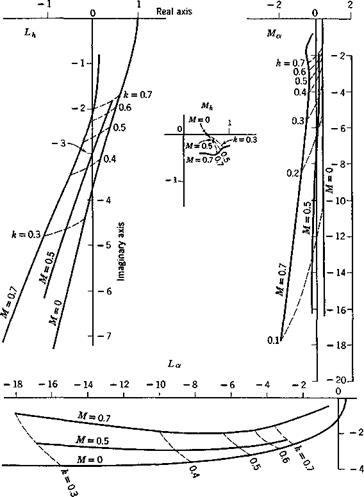
that these equations may be valid. In the theoretical derivation of these coefficients (Chapters 13 and 14), the fluid is assumed to be nonviscous so that Mt, etc., are functions of the Mach number and the reduced frequency. For a real fluid, they are also functions of the Reynolds number. Figure 6.16 show the theoretical curves of the complex numbers
|
Fig. 6.16. Theoretical values of the complex numbers Lh, Lx, Mh, and Мл for various Mach numbers and reduced frequencies. A vector drawn from the origin to an appropriate point on a curve gives a complex number (real part, abscissa; imaginary part, ordinate) which is the value of Lh, etc., given by the linearized theory. Note the difference in scales between Lh, Mh and La, Ma. |
Lh, Lx, Mh, Mx at several Mach numbers with the reduced frequency к as a parameter.
The source references from which the aerodynamic coefficients Ц, Mit etc., can be obtained are reviewed in §§ 13.6 and 14.7. Throughout the literature various notations and forms of the coefficients have been used. A comparison between the notations of different authors is given in Tables 13.1 and 14.2. The notations used in Eqs. 10 through 13 are introduced in Army Air Force Technical Report 4798, (1942), by Smilg and Wasserman.
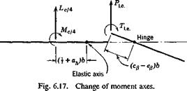
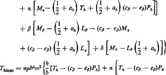
The aerodynamic forces and moments about the elastic axis of the wing and the hinge line of the aileron can be easily computed from Lcli, Мец, Ple, and Tl e. Let the force and moment at the elastic axis be Lb a and Me a,, respectively, and the moment about the aileron hinge line rhinge. From Fig. 6.17 is it clear that
Me.&. — Мсц + Lct4 (I + ah)b
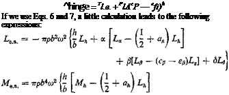 |
 |
(14)
+ m – – ev)(pe + г,) +
— S[Ts — Рв(ср — Сд)]|
The Equations of Motion. By a summation of the inertia, elastic, damping, and aerodynamic forces, we obtain the equations of motion in a manner described in § 6.8. In the following discussions, we shall assume that the tab is geared to the aileron so that
d = nfi (16)
where n is a proportional constant. The rigidity of the tab constraint about its hinge is considered as infinite. The equation of motion for the tab can therefore be omitted.
|
|
Denoting the time derivatives by dots, we obtain the following equations of motion:
mh + Sx& + (Sp + nS6)fi + (1 + igh)Khh + Lea = 0 Sji + ІЛ + [(ер – ah)bSp + Ip + nh + b(dfi – ah)nSefi
+ (1 + ig*)Kxx – Me. a. = 0 (17)
Sph + [Ip + Ь{сц — ah)Sf,]a + [f + nh + b(dp – Ср)п8в]$
+ (1 + igpWpfi — Thinge = 0
where
m = mass of wing-aileron-tab (per unit span)
Sx — static moment of wing-aileron-tab about wing elastic axis (per unit span)
Sp = aileron-tab static moment (per unit span) about aileron hinge line Sp — tab static moment (per unit span) about tab hinge line
Ix = mass moment of inertia of wing-aileron-tab about wing elastic axis
Ip — mass moment of inertia of aileron-tab about aileron hinge line Is = mass moment of inertia of tab about tab hinge line
Let us assume that flutter exists. The wing thus can oscillate harmonically as given by Eqs. 2 so that
h — — aPh, a = — ю2а, Д = — a>2/3 (18)
Substituting Eqs.. 15 and 18 into 17, and dividing the first equation by ттрЬ3а>2 and the other two by ттрЬ*оз2, we obtain
A – + Ву – f* Cft — 0 b
![]() h
h
D – + Ea. + Fft = 0 b
![]() where
where
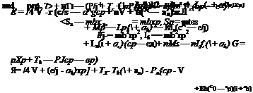
A = (x
В — i-ixa – j – 1-j – L}L(h “г ^/:)
С = /л{хр – f- nxg) + Lp — Lz(cfj — ep) + nLe
|
(1 + ig*) |
 |
|
D — pxx + Mih — Lh{ + ah)
If flutter exists, h, a, /9 do not vanish identically. Such a nontrivial solution exists when and only when the determinant of coefficients in Eqs. 19 vanishes:
![]() ABC D E F = 0 G H I
ABC D E F = 0 G H I
This characteristic equation involves the following real variables, U, со, к, p, coh, cox, wp, gh, gx, gp, and parameters defining the geometrical and mass distributions of the airfoil. Since Eq. 21 is an equation with complex coefficients, and since the real and imaginary parts of the determinant must vanish separately, it is actually equivalent to two real equations for these real variables. It can be used to determine any two of these variables, while others must be specified. The choice of particular variables to be considered as the unknowns depends on the information desired and the expediency of calculation.
When Eq. 21 is satisfied. Eqs. 19 may be solved for the ratios A/6:a:/5, which are complex numbers showing both the amplitude ratios and phase relationship.
Application of the Two-Dimensional Analysis. Regarding the two – dimensional airfoil as a typjcal section of a three-dimensional wing, and adjusting the spring constants in such a way that the frequencies coh, cox, etc., coincide with the actual uncoupled free vibration frequencies of the wing, while the mass and geometric properties are taken as those of a typical section, one may expect that the critical flutter speed calculated for the two-dimensional case approximates that of the actual wing. This was shown to be true by Theodorsen and Garrick6-22 for wings without appreciable sweep angle, without large concentrated mass, with more or less uniform distribution of structural properties across the span, with straight elastic and inertial axes, and with high chordwise rigidity. The location of the typical section is of some importance. Generally it is taken in the neighborhood of 0.7 span from the root, or at the mid-span of the aileron.


