Hybrid Method
Euler and Navier-Stokes solvers employ dissipative schemes to ensure the stability of the computation, either built into the numerical scheme or added artificially as a supplemental viscosity term. The dissipative property of those schemes works well with discontinuities such as shock waves, but has an adverse effect on discontinuities such as contact discontinuities and vortex sheets. It has been known for a long time that these schemes dissipate contact discontinuities associated with the shock-tube problem and vortex sheets trailing a finite wing, helicopter rotor, propeller and wind turbine. In the case of turbine flow, the influence of the vortex sheets is rapidly lost, which has an effect on the blade working conditions by not accounting for induced velocities contributed by the lost part of the wake.
On the other hand, the vortex model described earlier can maintain the vortex sheets as far downstream as needed, but cannot handle large span-wise gradients resulting in particular from viscous effects and separation.
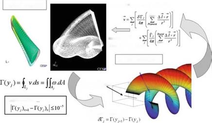
In the rest of this section, we will present some results of the hybrid method which consists in coupling a Navier-Stokes solver with the vortex model, the former being limited to a small region surrounding the blades where the more complex physics can be well represented, and the latter being responsible to carry the circulation to the far field and impress on the Navier-Stokes’ outer boundary the induced velocities
 Biot-Savart Law (discrete)
![]() Vortex
Vortex
Boundary of
![]()
Navier-Stokes Zone
Fig. 10.21 Coupling methodology accurately calculated by the Biot-Savart law. This new approach has been found to be both more accurate and more efficient than full domain Navier-Stokes calculations, by combining the best capabilities of the two models.
The coupling procedure is described in Fig. 10.21. It consists in calculating the Navier-Stokes solution with boundary conditions that only account for incoming flow and rotating frame relative velocities at the outer boundary of the domain. The solution obtained provides, by path integration, the circulation at each vortex location along the trailing edge of the blade and the Biot-Savart law allows to update the velocity components at the outer boundary of the Navier-Stokes region by adding the wake-induced contributions. This closes the iteration loop with a new Navier – Stokes solution. It takes approximately five cycles for the circulation to be converged with ЛГ < 10-5.
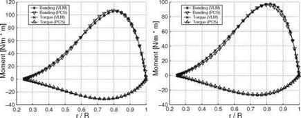
As an ideal test case for the hybrid methodology, an optimized turbine blade of a two-bladed rotor was designed with the optimization vortex code and analyzed with the coupled solver at the same design conditions for which the flow is attached and viscous effects are minimum. The results of inviscid and viscous calculations are compared with the vortex code on the global thrust, bending moment, torque and power as well as spanwise distributions in Table10.2. The global results are in excellent agreement with less than 1 % difference in power in the inviscid simulation and 7 % in the viscous one. The comparison is also excellent for torque and bending moment distributions as shown in Fig. 10.22 for inviscid and viscous cases.
The true benefit of the hybrid code resides in the simulation of the flow past a rotor when blades experience significant viscous effects that trigger large spanwise gradients. The strip theory assumption no longer holds and the flow becomes truly three-dimensional on the blade and cannot be accurately described by 2-D viscous
|
Table 10.2 Comparison of global results on test case
|
|
Fig. 10.22 Vortex model (VLM) and hybrid code (PCS) comparison: inviscid (left) and viscous (right) torque and bending moment distributions |
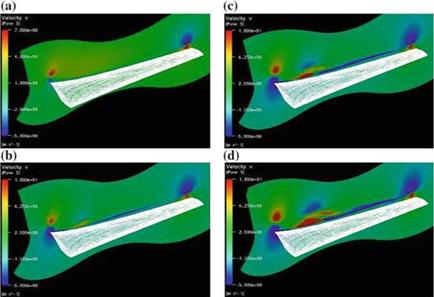
polars. The NREL test results have been a remarkable resource for evaluation of code prediction capabilities, ranging from simpler, steady, attached flow cases at low speed, to more challenging separated flows at higher speeds, as well as unsteady flow in presence of yaw and tower interaction. The hybrid method has been very successful at capturing the formation of a separation bubble on the suction side of the blade at about 9m/s, located at the 30 % blade span, that evolves into a “tornado vortex” rotating counter to the root vortex, see Fig. 10.23. The view is of the upper surface of the blade (suction side), with the blade root on the left and the blade tip on the right. At 7m/s the flow is fully attached. The cross-section by a plane perpendicular to the wake, a short distance of the trailing edge, displays the root vortex rotating clockwise and tip vortex rotating counter-clockwise, visualized with the spanwise velocity component v. As the incoming velocity increases to 9m/s, the wake of the blade, not visible before, now can be seen spanning the whole blade and a more defined structure appears at the 30 % location. The latter evolves into a strong vortex at 10 m/s whose counter-clockwise sense of rotation is opposite to that of the root vortex. At the higher speed of 11 m/s, the whole blade is stalled, yet the tornado vortex, as it has been called, has grown and has possibly produced another vortex at its lower right, rotating clockwise [17].
|
Fig. 10.23 Development of a well-defined viscous feature above the NREL blade |


