LONGITUDINAL CHARACTERISTICS OF WING-FUSELAGE COMBINATIONS
The basic components of an airplane are wing and fuselage. Their longitudinal characteristics influencing stability are presented here.
Stream Curvature. The longitudinal moment of airfoil sections are treated in the Chapter II as a function of the type and operating conditions. When using their characteristics, it must be realized that airplane wings, always having a finite span, impart a permanent downward deflection upon a certain stream of air. Since the deflection takes place within the chord of the wing, the effective camber of its section is reduced. The corresponding reduction of the usually negative free or zero-lift pitching moment coefficient is approximately:
A Cmo= + 0.044/A (7)
which means that for A = 4.4, for example, the aerodynamic center is shifted forward 1% of the wing chord. Since most of the Cmo values presented for airfoil sections in Chapter II, stem from tests on wings with A ■= 6, the difference as per equation (7) is usually unimportant in the analysis of wings having conventional aspect ratios.
Aerodynamic Chord (3). Airplane wings are usually not rectangular accordingly their chord length varies along the span. A mean chord, to which pitching moments can be referred, should account for the distribution of lift (load) across the span. If possible, the mean chord should represent the aerodynamic characteristics of the wing as to magnitude and location. This can be done for “straight” and untwisted elliptical plan forms:
9
5 = {2Ы)£~(c dy) = (S/3-гг) cx= 0.85 c* (8)
where s = b/s = half span, and cx = maximum chord (in the center). The location of the “mac” chord (equation 8) is at
5
y/s = (2kS)£ (cy/dy) = (4/Зтґ) s = 0.42 s (9)
Length and location of the chord indicated by these two equations, represents that of an imaginary equivalent “rectangular” wing. Therefore, when giving the wing some angle of dihedral, the (0.42 s) station can be expected to indicate the vertical location of the center of lift. However, wings are rarely elliptical; and if they are, they may be twisted, they will be combined with a fuselage, and they may carry partial-span flaps or engine nacelles. In short, their lift distribution will not really be elliptical. Assuming, on the other hand, that the load distribution of a plain rectangular wing be elliptical, its mean aerodynamic chord (equal to the geometric chord) would then be located at у = 0.42 s, while it actually is in the vicinity of 0.46 s.
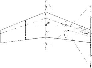
Tapered Wings. The pitching moment characteristics of tapered wings as derived from their theoretical lift distribution, are tabulated in (3,c) as a function of taper and aspect ratio. The use of these results is not very practical, however, and is not always realistic. A better definition of length and location of the mean aerodynamic chord, reflecting and approximating the findings in that report, and the result of equations (13) and (14) as well, is shown in figure 2. The lateral location of the “mac” varies between у = (l/3)(b/2) for zero taper ratio (as in doubly triangular or “diamond” wings) and у = 0.5 for rectangular plan forms. The chord length increases from c = (S/b) as for rectangular plan forms to (4/3)(S/b) for zero taper ratio.
|
Figure 2. Graphical determination of the mean aerodynamic chord and the aerodynamic axis of a tapered wing. |
(2) General treatment of longitudinal stability:
a) Braun, Rpt IB6 Ringbuch Luft Tech, 1940; also Lecture at AF Inst Tech, WP AF Base, Ohio, 1948.
b) Diehl, Engineering Aerodynamics, 1928 & 1936, Ronald Press.
c) Zimmerman, Analysis, NACA T Rpt 521 (193.5).
d) Gilruth, Prediction, NACA T Rpt 711 (1941).
e) Gates, Longitudinal Stability, ARC RM 1118 (1927).
f) Perkins-Hage, Performance Stability Control, New York 1950.
g) Babister, Aircraft Stability and Control, Pergamon Press, Yol. 1 1961
(3) Determination of aerodynamic chord and center:
a) Crean, A’Center, The Aircraft-Engineer, April 1936.
b) Diehl, Mean Aerodynamic Chord, NACA T Rpt 751 (1942).
c) Anderson, Tapered Wings, NACA T Rpt 572 (1936).
d) Lachmann, Tapered-Wing Characteristics, Flight, Oct. 1936.
e) Blenk, Stream Curvature, ZaMM 1925 p 36.
This “mac” definition, is generally used in all but the “old” reports of the NACA. However, in a wing with 0.5 taper ratio (as in the illustration) the mean aerodynamic chord is 1.02 S/b, and its location is at у = 0.45 s. The mean chord S/b at the position of 0.42 s (as in equation 9) might, therefore, as well be used in many practical wing shapes. The wing’s aerodynamic axis, connecting the aerodynamic centers (or the quarter points) on the mean chords, moves up together with the two wing panels, when they are given dihedral.
Wing Moment. In conventional mid-wing and low-wing configurations (as in figure 1, for example), the CG is essentially at the level of the wing. In a typical high-wing or even “parasol” type arrangements, the wing can be at an appreciable distance above the CG. In such a case, the longitudinal force (primarily the tangential component of the lift) of the wing has to be included in the analysis. In reference to the CG, (the hinge axis about which the airplane is pitching) the wing forces produce the moment (marked by the subscript “g”):
Cmo= Cmo+ (ax/c)Cl + (z/c)CD5 – (z/c)(do: /dCL )Cl
(10)
where x = g — a — longitudinal distance between CG and the wing’s aerodynamic center (measured parallel to the zero lift line, positive when the AC is forward of the CG) and where z = vertical distance (positive when the AC is above the CG). As suggested before, the term containing the section drag coefficient may usually be disregarded. The “lift angle” in the last term is that in two-dimensional flow thus independent of the aspect ratio, theoretically equal to 0.5/rr and actually ^10° (nr/180) ~ 0.17 (in radians). This term represents the tangential, forward – directed and thus “negative” component of lift. Using (4) the lesser value 0.15, differentiation of the equation yields the stability contribution of the wing
dCm/dCL = (л x/c) – 0.3 (z/c) CL ; сІД CWdC* = 0.3 (z/c)
(11)
where 0.3 = 2(0.15). Thus with the airplane’s CG not at the level of the wing’s AC, dO^/dC^ can no longer be expected to be constant as a function of lift coefficient or flying speed. In case of a low-wing configuration (provided that the CG is really above the mean aerodynamic chord of the wing) the wing’s dCm/dCL may grow less negative (less stable) as CL is increased, while in a high – wing airplane, the opposite is true. [99]
Lift Due to Fuselage. The lift of conventional low wing plus fuselage configurations is generally higher by some essentially constant amount than a high wing combination. Depending upon fuselage shape and size the lift – curve slope of the combination tends to be somewhat increased, particularly for mid-wing configurations. An example of such interaction is presented in figure 3. Principle results are as follows:
(a) The lift-curve slope of a wing and fuselage together is some 5% higher than that of the wing alone.
(b) When changing the angle of attach of the wing against the fuselage body (kept at zero angle of attack, the lift-curve slope is some 5% lower than that of the wing alone.
WING 0012 RECTANGULAR A = b/c = 6 FUSELAGE ROUND WITH l/b = 2/3? l/d = 6
|
|
a) WING ALONE (NO FUSELAGE ) dC /doc = 0.077
b) WING PITCHED AGAINST FUSELAGE (KEPT AT o< =0) =0.073
c) WING PLUS FUSELAGE TOGETHER = °*080
d) A TAPERED WING (7,c) YIELDS 0.077; 0.074; 0.080
Figure 3. Influence of a fuselage upon the lift of a wing as tested (7,b) in NACA VDTunnell at Rc = 3(10)^ or RF – 8(10)fo.
Regarding (b) it must be mentioned that in the design of airplanes, the wing is usually set at a certain positive angle of a few or several degrees, against the fuselage. It must be noted that such an angle of incidence (denoted by i) produces a certain lift differential (negative in comparison to the lift of the wing alone). However, the lift-curve slope of the wing plus fuselage combination is basically not affected by that angle.
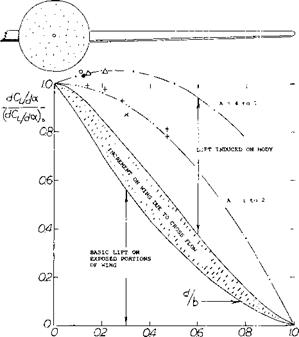
Cross Flow. The fuselage does not fully replace the lift of the portion of the wing “covered”. However, as explained in the Chapter XIX, a cross or “2oc ” flow (5) develops around the sides of every cylindrical or streamline or “round” fuselage body when inclined at an angle of attack against the wind. As a consequence of this cross flow which is increased by the upwash ahead of the wing the angle of attack at, and lift on the wing roots are also increased. However, when rotating the wing against the fuselage operating at zero angle of attack as in figure 3 (test b) the cross flow does not develop and in this case dCL/dai is reduced below the value for the wing alone. In airplanes (where wing and fuselage are rigidly attached to each other) the cross flow effect is so strong that the lift of wing-fuselage combinations grows at first with the d/b ratio, as illustrated in figure 4. After reaching a maximum ratio of ~ 1.06, in the vicinity of d/b = 0.15, the combined lift reduces, however, tending toward zero as the fuselage diameter would ultimately approach the size of the span.
d——————————- 6
|
|
Moment Due to Fuselage. As explained in the Chapter XIX the fluid-dynamic moment originating in slender fuselages, consists of two components:
1) From a positive lift on the forebody due to potential flow
2) From the negative lift on the afterbody as a result of the vortex flow.
In conventional wing-fuselage combinations, the angle of attack of the fuselage’s tail within the wing’s field of downwash, is comparatively small. For the purpose of longitudinal stability analysis it will therefore assume that the “second” (stabilizing) component of moment is zero. This is the moment produced by boundary-layer accumulation and “viscous” lift originating at the upper (suction) side of the fuselage, near its trailing end. The longitudinal moment of fuselages; in combination with a wing, can then be expected, essentially to be a “free” moment (with no resultant life force). Also from Chapter XIX the destabilizing free moment of round fuselage-type bodies in free flow, is approximately
MF /(яМ) = or ;
orCmF=MF/(qCd’)b)= oc° /720 = (*773 (12)
where ’d’ = maximum width, equal to the maximum diameter of the affected volume of air, 5. is the angle of attack in radians S0 = (’d’) тґ/4, and Л – length of the body. Referred to the dimensions of an airplane:
A(dCjdoc) = (S0/S)(i/c)
A(dCWdCL) = (S0/SX^/cXdoc /dCL ) (13)
where (S0/S)(^/c) should not be confused with the tail “volume” of airplane configurations.
a JUNKER, RECTANG LOW WING A = 6, SEE (fc, e)
о NACA, RECTANGULAR MID WING A = 6 (7,b)
• OTHER LARGER ASPECT RATIO COMBINATIONS ■+ JUNKERS, HIGH OR LOW WING, SEE (€>,e)
x DVL, TRIANGULAR WINGS, A = 1.3 & 2, SEE (f>,e)
0 NACA, A = 3 TAPERED, WING COMPONENT (6,g)
AS DERIVED IN (6,e) THE COMPONENTS OF LIFT IN LARGER
ASPECT RATIOS ARE APPROXIMATELY AS FOLLOWS:
a) EXPOSED PORTIONS OF WING: L/Lq = (1 – (d/b))5//J
b) DUE TO CROSS FLOW (UPWASH): L/Lq = (d/b)(l – (d/’b))[100] [101]^3
c) INDUCED ON BODY BY WING: L/Lq = (d/b)(l + (d/b))(1 – (d/b))^3
A SIMILAR SET OF EQUATIONS LEADS TO THE FUNCTION AS PLOTTED
FOR SMALL ASPECT RATIOS.
Figure 4. The lift curve slope of wing-fuselage combinations as a function of the diameter (or width) ratio d/b.
(6) Lift of wing-fuselage combinations:
a) Vandrey, Theoretical Analysis, Lufo 1937 p 347.
b) Multhopp, Fuselages, Lufo 1941 p 52 (NACA TM 1036).
c) See results in references under (7), such as b) & c).
d) Liess, Lift and Downwash Analysis; see (14,a).
e) Hoerner, T Rpt F-TR-1187-ND Wright Patterson AF Base (1948).
f) Lange, Small A’Ratios, ZWB Doct UM 1023/1 to 5.
g) Mayer-Gillis, Load Distribution Among Wing Fuselage Tail, L50J13, L51E14a, L53E08.
h) Analysis is found in NACA RM A51G24, L51J19 & L52J27a.
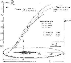
Wing Interference. The magnitude of the free fuselage moment is increased along the forebody by the upwash induced by the wing. Moment differentials obtained from wing models tested (7) with and without fuselage (essentially in mid-wing locations) have been evaluated. Figure 5 shows how those differentials vary as a function of the longitudinal location of the wing. The moment reduces to approximately zero as the wing moves toward the nose of the fuselage and reaches and crosses the theoretical level for a wing position approximately at half the fuselage length. A particular example for tail-fuselage interaction is shown in figure 6. The pitching moment derivatives given are referred to airframe dimensions. The moment ratio 0.0028/0.0068 = 0.41 using theory, equation 12 fits reasonably well into figure 5, while the ratio 0.0028/0.0051 = 0.55 from tests of fuselage alone would not. It seems that the body shape alone exhibits a stabilizing “viscous” component A(dCrf/doc)^ — 0.002 (on account of its rather bluff rear end) so that dC^doc = 0.0051 as tested, instead of 0.0068 as predicted by theory.
|
|
|
A(dCm/dof ) a(dCm/dCL) EXPLANATION |
|
THEORY (+) EQUATION (12) +0.0068 IN PRESENCE OF WING +0.0028 FUSELAGE ALONE, NO WING +0.0051 |
|
+0.097 IF STREAMLINE END +0.040 REDUCED SEE F.5 +0.073 HAS "BLUNT" END |
(+) USING RATIOS LISTED BELOW dCL/da = 0.070
INDICATING FORWARD SHIFT
OF NEUTRAL POINT – дх/с
WING: b/c =5 R = 4(10)5
t/c = 12% RECTANGULAR c
FUSELAGE: 1/d = 7
1/c = 5
d2/S =0.1
Figure 6. Example (17,a) for the contribution of a fuselage body to the pitching moment of an airplane configuration.
|
|||||||||||||||||||
|
|||||||||||||||||||
Upwash/Downwash. At 1.0, as in the combination
of a horizontal tail surface and fuselage (where most of the body length is ahead of the wing the moment differentials plotted in figure 5, surpass the value as in undisturbed free flow). There is some upwash ahead of the wing, which accounts for this increment of the destabilizing body moment. The downwash behind the wing can, [102]
Fuselage Shape. The longitudinal fuselage edges, such as a rectangular (instead of a round) cross-section shape, increase stability slightly when applied aft of the wing and particularly near the tail end and reduce stability when used ahead of the wing. Characteristics of wing-body combinations as affected by the fuselage’s cross-sectional shape, are listed in figure 7. Both the rectangular and the upright elliptical fuselage shape, present pitching moments which are less positive (less unstable) than the round shape. In the elliptical shape, it seems that the forebody causes less cross flow, while the afterbody of the “square” shape seems to be more stable on account of its lateral edges. When adding a radial-type engine in the nose of the fuselage, stability of the combination (without tail) is little affected. All of the configurations shown in figure 7 have fuselage moment ratios below unity. Figure 5 demonstrates, however, how much that ratio depends upon the longitudinal position of the wing along the fuselage.
 |
||
ALL VALUES IN PARENTHESES ARE FOR CONFIGURATIONS WITH WING-ROOT FILLETS, a) AT Rc = 3(10)6 IN VARIABLE DENSITY TUNNEL; Rf = 8(10)6.
Ы WITH 0018/09 TAPERED WING HAVING CHARACTERISTICS SIMILAR TO THE 0012. c) BREAK-AWAY OF LIFT AT CL = 1.0; ALL OTHERS BREAK CLOSE TO CL>
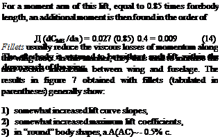
FUSELAGES WITH //b = 2/3 or / = 4 c; ROUND SHAPE AS IN FIGURE 3.
WHEN TESTED ALONE, THE RECTANGULAR FUSELAGE SHAPE PRODUCES A(dC /dCL)= +.03 (BASED ON WING DIMENSIONS, AROUND THE //4 AXIS). THE ROUND FUSELAGE PRODUCES ^(dCn/dCL) = + 0.05.
When applied to the fuselage with rectangular cross – section shape, fillets do not have much of an effect.
![]()
Figure 7. Lift and longitudinal characteristics of a wing in combination with various fuselage shapes, as tested (7,b, c) m NACA VDT.
The Flying Boat Hull, shown in figure 8 produces, in presence of the wing, positive (bow up) pitching moments which are larger than predicted by equation (12). We may assume that the hard-chined bottom of the forebody (ahead of the CG at ^ 0.4 of the length) may produce some lift, in the same manner as a small aspect ratio wing. Using the corresponding function given in Chapter III the forebody lift, based on the square of the hull beam, corresponds to
dCLb /doc =7/7360 = 0.027
|
IN PRESENCE OF THE WING: dC /dor° = 0.020 EXPERIMENTAL ^ = 0.014 EQUATION (20) =0.011 AS PER FIGURE 6 = 0.020 INCLUDING E(15) |
ЛС = – 0.02 ON WING DIMENSIONS = – 0.20 ON BODY DIMENSIONS
Figure 8. Pitching moment characteristics of or due to the hull of a flying boat (7,f). The definition of the coefficient is Cnn = M/(q
bt )•
Fuselage Ducts. The principle stated above, whereby fuselage moments are proportional to the volume of air affected by them (equation 12) also applies to various other bodies (such as to external stores, for example) and to the addition of such bodies to wing or fuselage. Figure 9 shows as an example, the influence of inlet ducts for jet engines, simulated by adding solid half bodies to the sides of the fuselage. Moments of the configurations referred to the volume parameter (£d2) of the basic fuselage body, are plotted in the graph versus the “span” ratio ’d’/d show,
(a) Lateral ducts with constant length, when exposed to an angle of attack, cause the unstable moment derivative of the configuration, approximately to grow in proportion to the “span” ratio, as postulated by equation (12).
(b) In configurations with the ducts on top of or below the fuselage, the pitching moment essentially remains unaffected. Again, the moment derivative corresponds to the dimension 4d’ measured normal to the direction of angular displacement.
(8) Characteristics of ducts, stores, et cetera:
a) Jaquet, Airplane With Ducts, NACA TN 3481 (1955).
b) Wilson, Twin-Engine Nacelles, NACA W Rpt L-428 (1940).
c) Crigler, Propeller in Pitch & Yaw, NACA TN 2585 (1952); also Comparison with Experiments, W Rpt L-362.
d) Silvers, Influence of Missiles, NACA RM L54D20.
О A = 2 WING 0.6 TAPER RATIO


