Our heavyweight helicopter equal in the world does not have
In Rostov started production of the most load-lifting rotary-wing car The Russian holding «Helicopt[...]

Everything about aircrafts and helicopters. News and events in aviation worldwide. Civil, transportation, military helicopters and airplanes.

Everything about aircrafts and helicopters. News and events in aviation worldwide. Civil, transportation, military helicopters and airplanes.

Everything about aircrafts and helicopters. News and events in aviation worldwide. Civil, transportation, military helicopters and airplanes.

Everything about aircrafts and helicopters. News and events in aviation worldwide. Civil, transportation, military helicopters and airplanes.


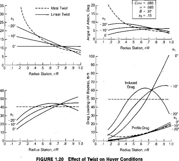
The primary effect of nonideal twist is to require more induced power than ideal twist. Figure 1.20 shows calculated distributions of pitch, induced velocity, angle of attack, and drag loading for several values of twist for the rotor of the example helicopter at its design gross weight. Several observations may be made about this series of plots:
• Ideal twist gives constant induced velocity and constant induced drag loading.
• A linear twist of —20° comes closest to simulating ideal twist.
• All the linear twist curves have approximately the same pitch at the 75% blade station. (This is a good rule of thumb for all thrust levels.)
• The profile drag loading with ideal twist is high near the root because of high angles of attack.
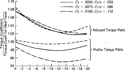
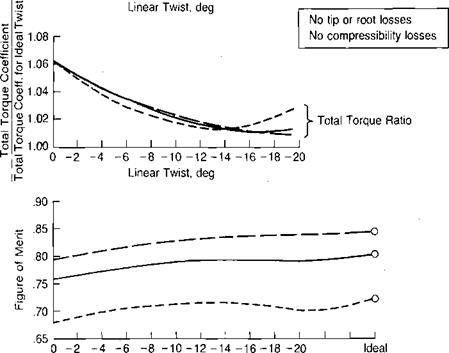
Figure 1.21 shows the effect of twist on hover performance of the example helicopter. From this series of plots, it may be observed that:
![]()
|
|
|
|
|
• Increasing the twist decreases the induced torque from 8% more than ideal twist to about 2% more.
• It is possible to have too much twist, especially at the light disc loadings.
• A rotor with linear twist in general has less profile torque than a rotor with ideal twist because of the high inboard angles of attack noted on the previous figure.
• Going from no twist to ideal twist can raise the Figure of Merit about 5%.
• Most of the potential benefit of twist is realized in the first 10° of twisting.
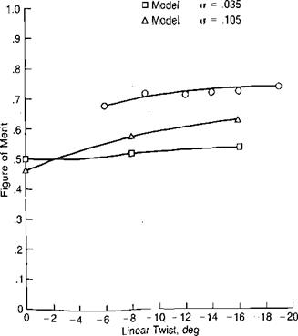
Figure 1.22, based on references 1.5 and 1.6, shows that the theoretical effects of twist are verified by model tests.
|
|
|
Linear Twist, deg Twist FIGURE 1.21 Effect of Twist on Hover Performance |
It should be pointed out that whereas high twist is beneficial in hover, it produces high vibratory loads in high-speed forward flight and thus is usually limited to some compromise value. Currently this compromise is in the neighborhood of —5° to —16°.
One secondary twist consideration is that the negative values that are beneficial in reducing the angles of attack in powered flight are detrimental in autorotation. Reference 1.7 also presents test data showing that the optimum twist for hovering in ground effect is significantly less than is optimum for hovering out of ground effect.
|
О Full-scale <r = .115
FIGURE 1.22 Effect of Twist on Measured Rotor Performance |
Sources: Clark, “Can Helicopter Rotors Be Designed for Low Noise and High Perform, ance?” AHS 30th Forum, 1974; Landgrebe, “An Analytical and Experimental Investigation of Helicopter Rotor Hover Performance and Wake Geometry Characteristics,” USAAMRDL TR 71. 24, 1971.