Phase Method
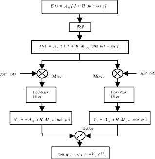
The phase method is a frequency-domain technique that detects a phase shift of the luminescent signal with respect to the modulated excitation light (Torgerson et al. 1996; Torgerson 1997). Figure 6.2 shows the working principle of the phase method with a lock-in amplifier. For the sinusoidal excitation light E(t) = Am[l + H sin( a t)] , the corresponding modulated luminescent signal from a photodetector is mixed with the in-phase and quadrature reference signals, i. e., sin( a t) and cos( a t). Next, the use of a low-pass filter generates the DC components Vc = – Am %H Meff sin(p) and Vs = Am % HMeffcos(^), which are related to the phase angle ^ between the luminescent emission and excitation light. A
ratio between these filtered signals yields a quantity tan(p = mx = – Vc/Vs that is uniquely related to the lifetime for a fixed modulation frequency. Therefore, pressure is given by
The sensitivity of the phase angle ^ to pressure is defined as
![]()
![]() dp = а дт
dp = а дт
dp 1 + (m )2 dp
The optimal modulation frequency to achieve the maximum sensitivity Sp is
ax = 1. (6.16)
It must be noted that the maximum sensitivity to pressure does not tell the whole story if the noise is not taken into account. Besides good sensitivity to pressure, the signal-to-noise ratio (SNR) should be also considered in order to select the optimal modulation frequency. At a higher frequency, the modulation amplitude
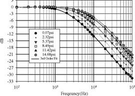
and DC components from PSP decrease, resulting in a lower SNR. Figure 6.3 is a Bode plot showing the response of a typical PSP, PtTFPP in polymer/ceramic composite, to the modulation frequency; the behavior of this PSP is very close to the first-order system.
|
Fig. 6.2. Block diagram of the phase method |
|
Fig. 6.3. The Bode plot of PSP (PtTFPP in polymer/ceramic composite) at -30°C. From Lachendro (2000) |


