Swept and delta wings
Owing to the dictates of modern flight many modern aircraft have sweptback or slender delta wings. Such wings are used for the benefits they confer in highspeed flight – see Section 6.8.2. Nevertheless, aircraft have to land and take off. Accordingly, a text on aerodynamics should contain at least a brief discussion of the low-speed aerodynamics of such wings.
5.7.1 Yawed wings of infinite span
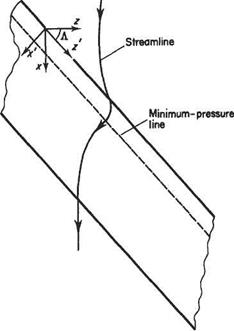
For a sweptback wing of fairly high aspect ratio it is reasonable to expect that away from the wing-tips the flow would be similar to that over a yawed (or sheared) wing of infinite span (Fig. 5.36). In order to understand the fundamentals of such flows it is helpful to use the coordinate system (У, y, z’), see Fig. 5.36. In this coordinate system the free stream has two components, namely Ux cos Л and sin Л, perpendicular and parallel respectively to the leading edge of the wing. As the flow
![]()
|
approaches the wing it will depart from the freestream conditions. The total velocity field can be thought of as the superposition of the free stream and a perturbation field (г/, V, 0) corresponding to the departure from freestream conditions. Note that the velocity perturbation, W = 0 because the shape of the wing remains constant in the z! direction.
An immediate consequence of using the above method to construct the velocity field is that it can be readily shown that, unlike for infinite-span straight wings, the streamlines do not follow the freestream direction in the x—z plane. This is an important characteristic of swept wings. The streamline direction is determined by
![]() (5.65)
(5.65)
When li = 0, downstream of the trailing edge and far upstream of the leading edge, the streamlines follow the freestream direction. As the flow approaches the leading – edge the streamlines are increasingly deflected in the outboard direction reaching a maximum deflection at the fore stagnation point (strictly a stagnation line) where 1/ = Uoo- Thereafter the flow accelerates rapidly over the leading edge so that 1/ quickly becomes positive, and the streamlines are then deflected in the opposite direction – the maximum being reached on the line of minimum pressure.
Another advantage of the (У, y, zf) coordinate system is that it allows the theory and data for two-dimensional aerofoils to be applied to the infinite-span yawed wing. So, for example, the lift developed by the yawed wing is given by adapting Eqn (4.43) to read
£ = ^/0(tf«cosA)2S^j^ (a„ — ao„) (5.66)
where a„ is the angle of incidence defined with respect to the x! direction and ao„ is the corresponding angle of incidence for zero lift. Thus
a„ = a/cosA (5-67)
so the lift-curve slope for the infinite yawed wing is given by
dQ,_/dC^ CQS^ ^ 27tcosA (5.68)
da V d« Jw
and
LoccosA (5.69)


