The Biot-Savart Law
Each filament of the trailing-vortex sheet “induces” velocity components at every point on and around a wing. As mentioned in Chapter 5, the vortex sheet does not actually cause a velocity to be present at a point. Rather, the flow field associated with the vorticity coming from the wing is configured such that it may be thought of as being induced by the vortices present in the flow model. A method of calculating these induced velocities is sought here as a generalization of the predicted behavior of the point vortex in two dimensions (see Chapter 4).
The general Biot-Savart Law mathematically expresses the velocity induced at any point in space by an element of a curved vortex filament. In this form, it is sometimes used to calculate the shape of the wakes of helicopter blades.
In the analytical and numerical models discussed herein, the vortex sheet is assumed to be planar, which allows the Biot-Savart Law to be considered in a simpler form. More complex analyses allow the trailing-vortex sheet to distort due to self-induced velocity disturbances. The Biot-Savart Law is stated here without proof. However, when applied to the familiar two-dimensional point vortex as a special case, the law provides the anticipated result.
 |
 |
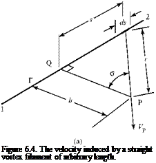
We consider a vortex filament of length 1-2 with a constant strength, as shown in Fig. 6.4. Let ds be an increment of length of the filament.
The Biot-Savart Law states (Fig. 6.4a) that if the filament and Point P are both in the same plane, then the velocity induced at the fixed but arbitrary Point P by an increment of filament, ds, is perpendicular to that plane and has a magnitude, dVP, given by
where r is the length of a line joining the increment of filament, ds, to Point P; PQ is the normal from Point P to the filament (of length h = constant); and the angle о is the angle that r makes with PQ. We recognize from geometry (Fig. 6.4) that with s as the distance between Q and ds, then:
h
— = cos о r
s 2
and — = tan o^ ds = h sec2 о do.
 |
||
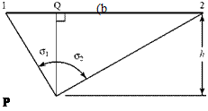
Substituting these relations as into Eq. 6.1 leads to an expression in terms of the variable о, the length h being a constant. Summing the contributions of all of the increments ds comprises a filament 1-2 of arbitrary length and orientation, as illustrated in Fig. 6.4b.
Note in Fig. 6.4b that if the end point(s) of the vortex filament lies to the left of the point of interest, P, then o2 is a negative angle.
If the vortex filament is infinite in extent, then sin oi ^ -1 and sin o2 ^ 1. Equation 6.2 then states that:
![]() Vp 2 nh’
Vp 2 nh’
Notice that this result agrees with the two-dimensional vortex behavior discussed in Chapter 4. The vortex filament in Eq. 6.3 is of constant strength, extends to infinity in both directions, and is perpendicular to the plane P-Q containing Point P. The Biot – Savart Law thus gives the expected result when applied to a problem corresponding to a two-dimensional point vortex.
If the vortex filament in Fig. 6.4 were only semi-infinite in length and extended from Q to infinity, then the limits of integration in Eq. 6.2 would be o1 = 0 and o2 ^ n/2, leading to:
![]() Vp 4 nh’
Vp 4 nh’
This result is useful later.
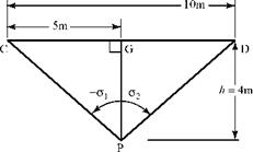
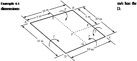
Required: Find the magnitude of the velocity induced by the vortex in a direction normal to the plane at Point P if Point P lies in the same plane.
Approach: The contribution of the four lengths of the vortex filament must be evaluated by applying the Biot-Savart Law, as expressed in Eq. 6.2. The limits of integration in this equation must be modified to reflect the different finite lengths of each segment of vortex filament.
Solution: Consider each segment in turn. The required angles are rounded off to the nearest degree, for convenience.
a. 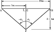
 |
Segment A-B:
"«■> = 4n(6)[si”(40°) – sta(-40°)] = 2ЇЛ<L28)
b.
![The Biot-Savart Law Подпись: FP<b) = " 8Ь,<50')] = Ж a40)](/img/3130/image624.gif) |
Segments B-C and A-D have the same contribution by symmetry. Thus,
c. Contribution of segment C-D:
|
|
VP(c) = <2>4iTj)[sin(51°> – sin(-51-)j = 1- a-56).
Adding the three results and substituting the given vortex strength:
VP = 18.5 m/s.
Appraisal: The given units may be verified by evaluating the units in Eq. 6.4 or in the vortex theory of lift, L’ = pVMT, where L’ is the lift per unit span (meter) and p is the density mass per cubic meter.
Notice that P-E, P-F, and P-G in turn play the role of P-Q in Fig. 6.4, whereas A-P and B-P, for example, play the role of the line of variable length r in Fig. 6.4 at two extreme end points. Extreme care must be taken so as to use the correct signs for Oi and o2.


