Use of Trailing Edge Tabs
On helicopter airfoils, trailing edge tabs are frequently used to help negate the pitching moment produced by positive camber over the leading edge nose region, while retaining the benefits of a high maximum lift achieved by the use of camber. An example is the HH-02 shown previously in Fig. 7.24. As shown in Fig. 7.25, the mean camberline near the trailing edge affects significantly the pitching moment, and also the zero lift angle of the section is altered. On early helicopter rotors, trailing edge tabs were used to move the aerodynamic center further aft to help control or delay the onset of torsional flutter. Today, this is done by better airfoil design. Furthermore, an aft aerodynamic center is desirable as less nonstructural mass has to be installed in the blade to achieve the proper net moment balance about the elastic axis of the blade for aeroelastic stability reasons.
By means of the thin-airfoil theory (Section 14.8) the contributions to the lift and moment from the tab can be obtained for a given tab size and angle of deflection. The problem was first examined experimentally by Wenzinger (1935). Assume that the ratio of the tab chord to the airfoil chord is given by E, as shown in Fig. 7.26, and the tab deflection angle is rj. An upward deflection of a tab makes the ordinates of the mean camberline more positive in the trailing edge region. As a consequence, the zero lift angle becomes more positive, and the lift and net pitching moment are reduced for a given AoA. The curvature of the camberline is zero for x < (1 — E) and takes a value rj for x > (1 — E). Thin airfoil theory gives for
![]() (7.79)
(7.79)
where 0t is the value of 9 at the tab, that is, 6t = cos 1{2E — 1). In a similar way, A and A2 can be evaluated as
 (7.80)
c

Camber from tab
(1 -E)c
Figure 7.26 Airfoil with a trailing-edge tab and thin airfoil model.
 |
The incremental lift and moment from tab deflection can, therefore, be written as
 |
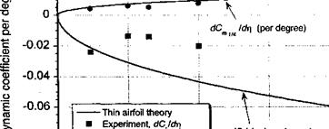
trailing edge tabs (or flaps) provided the tab deflection remains below 5°. If the deflection angle is significant, the adverse pressure gradients found in the region where the tab in initiated will lead to boundary layer thickening and a reduction of maximum lift and increase in profile drag. On contemporary rotors, small trailing-edge tabs are often apparent and are there to help track the rotor, but they are built into only a small part of the blade span.
![]()
![]()


![]()
![]()

-0.1
Figure 7.27 Effects of trailing-edge tabs on lift and pitching moment. Positive upward tab deflection. Data source: Collated results by Prouty (1986).


