Vertical Descent
The space age has discounted the old axiom that what goes up must come down. However, the statement still applies to the helicopter. Hence this section investigates the rotor aerodynamics of operating in a vertical descent with zero or partial power.
The operating state of a rotor, normal to its disk plane, has been historically characterized by the direction and magnitude of its thrust vector
|
(c) (d) |
|
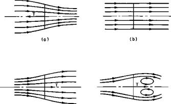
(e) Fig. 5-8. Working states of an airscreen: (a) normal; (b) zero-thrust; (c) windmill; (d) turbulent windmill; (e) vortex ring. |
and the resulting flow through the disk. The various states of flow are best visualized by starting with the rotor in the normal state of operation and then decreasing the thrust to zero, reversing its direction and then increasing its magnitude. In this manner the rotor passes consecutively through the normal, zero-thrust, windmill, turbulent windmill, and vortex-ring states. These states are illustrated in Fig. 5-8.
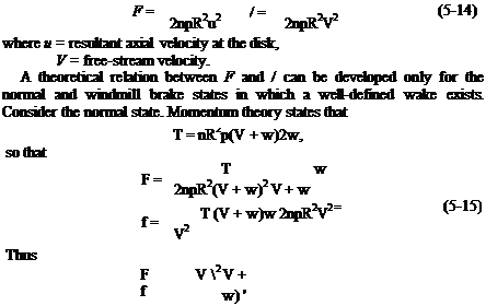
The analysis of a rotor in the turbulent windmill and vortex-ring states is difficult because of the irregularity of the nature of the flow through the disk and in the wake. Glauert [8] proposes the use of two parameters
![]()
|
|
 |

Solving for w from (5-15) we obtain finally
у = (1 – Л2. (5-16)
In the windmill brake area w subtracts from the free-stream velocity
T = nR2p(V – w)2w,
so that
j = (1 + F)2- (5-17)
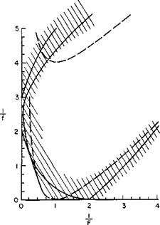
In the other operating states the relation between / and F must be determined experimentally. Several difficulties are encountered in doing this. The main problem is that the velocity u, as used in Eq. (5-14), is an “average” velocity through the disk, whereas, in the vortex-ring state the flow varies radically from a uniform distribution. Considerable disagreement exists among various investigators about the relation between/and F, particularly for values of 1 /F less than 2. Figure 5-9 presents the theoretical variation of 1 // versus l/F for the windmill brake and normal working states together with a band of experimental data which has been obtained to date.
In practice, it is sufficiently accurate to calculate the vertical descent velocity by simple momentum theory. The minimum sink rate of a typical helicopter is then approximately 60% of the vertical descent velocity and occurs at approximately the speed for best climb.
The limiting vertical descent velocity in autorotation can be found from simple momentum theory.
T = pA(VB — w)2w.
The limiting vertical descent velocity VD can be obtained from considerations of the transfer of kinetic energy from the flow to the rotor. However, it is most readily obtained by expressing VD as a function of w and finding the value
As stated previously, the minimum sink rate in autorotation occurs in forward flight and is approximately 60% of the value given by Eq. (5-18).


