Acceleration Phase
The acceleration phase is very critical as it determines the take-off velocity Vt. o. at the point where the pilot rotates the airplane to give it the incidence needed to begin climbing. The velocity V depends primarily on the power plant and the mass of the airplane. To a lesser extent it depends on the parasitic drags, aerodynamic and rolling friction drags. This is the reason why a high wing lift coefficient CLmax is needed in order to lift the highest possible weight. These can be modeled in more details with the acceleration code as
In this formulation, the thrust T [V] can be a more elaborate function of the velocity, say from wind tunnel measurements, although the previous linear model can be used when more detailed data is not available. The zero-lift drag Co0 will vary with velocity via the Reynolds number Re = p Vlref /jx based on the air density and dynamic viscosity, the velocity and the fuselage length lref. In general we will assume turbulent flow on most of the wetted area of the airplane. Therefore the viscous drag will be estimated as
Co0( Re) = Cf-f (11.38)
The reference drag coefficient, CDfref is estimated using the friction drag of each streamlined component and tables for blunt elements such as the landing gear of the airplane. The reference velocity is chosen typically as Vref = 20m/s. Accounting for the main wing, the tail, the fuselage and the landing gear, adding the different contributions with their corresponding reference areas, gives
Aref Cof ref = AmCom + AtCoft + AfCoff + Ag Cofg (11.39)
The induced drag is primarily due to the main wing because of the high lift coefficient, even during the rolling phase. The induced drag of the tail is neglected. The induced drag reads as previously
![]()
![]() C2
C2
CL
n eAR
The rolling friction is modeled with a coefficient of friction ak as
|
|
ak depends on the materials in contact and for rubber on asphalt a value ak — 0.03 is used. The normal force acting on the tires is the apparent weight of the airplane, where
1 2
Wapp — M9 — 2 p V ArefCL (11.42)
This model is transformed into a system of 2 first-order ordinary differential equations in 2 unknowns x and V as
dx _ v
dt = v (її 43)
ddv — (T[V]- 2PV2Aref (Cdo[V] + CDi) – akWapp[V]) /M K ;
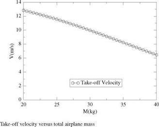
Integration is carried out with a 4th-order Runge-Kutta scheme and a time step At — 0.01 s. The total mass M is varied and a relation Vt. o.(M) is obtained for the take-off velocity achievable for different airplane masses. This result is important as it will determine the feasibility of taking-off and flying a round when running the equilibrium model. For an open class entry, the results are presented in Fig. 11.4.


