INFLUENCE OF PROPELLER SLIPSTREAM ON WINGS
Because the propulsion system must react on the air to produce thrust, the velocity in the slipstream is higher than in the free stream the magnitude is directly proportional to the disk loading. With a high disk loading the area of the slipstream is smaller than with light loadings for a given level of thrust. Thus, thrust systems such as propellers will have a large slipstream area with a relatively small increase in velocity. For this reason the propeller slipstream of tractor type airplanes will impinge on large portions of the airplane, the area of the wing and fuselage effected depending on the configuration. Airplanes have been designed to minimize slipstream effects by using pusher propellers. A notable example is the six engine pusher propeller B-36 airplane. Many other pusher propeller installations have been built but usually they never reached production. In the case of the B-36 the pusher configuration was selected as it was desired to eliminate the propeller slipstream effects on the wing and to maintain laminar flow.
With tractor installation it is possible to have an airplane configuration using ducted fans, turbofan engine or jet engines where the slipstream does not impinge on the airplane structure. Because the effects of the slipstream can be desirable as well as harmful, it may not be an advantage to eliminate all slipstream effects on the airplane. This, of course, will depend on the particular airplane and its performance goals.
(6) Slipstream Effects – Propellers:
a) Theodorsen, Static Propellers & Helicopter Rotors, AHS
25th Forum, 1969.
b) Jameson, A., Propeller-Wing Flow Interaction, NASA
SP-228; also NASA CR-1632.
c) Smelt & Davis, Lift Due to Slipstream, ARC RM 1788
(1937).
d) Stuper, Evaluation, Lufo 1935 p 267; 1938 p 181.
0 Bradfield, Airscrew and Wing, ARC RM 1212 (1929).
g) Kuhn, Wing-Propeller Combination, NACA T Rpt 1263
(1956); also Continuation, NASA D-17 (1959).
h) Kuhn, Propeller & Wing & Flap, NASA Memo 1-16-1959,
L.
i) AVA Gottingen, Wing in Slipstream, Erg I (1920) p 112.
6) At several propeller diameters aft of the disk, the wake expands with a 15 degree included angle like that of most streams.
7) 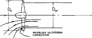
 The actual velocity imparted to the slipstream by the propeller consists of axial, radial and tangentional components of velocity, which are periodic in nature. Immediately downstream of each blade the velocity increment is a maximum. In between the blades the velocity increment is a minimum, but is still more than 50% of the peak. Except at zero and low speeds the radial velocity is small and can be neglected. The tangentional component of velocity in the slipstream is in the same direction as the
W propeller rotation.
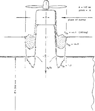
8) The increase of the axial velocity is not uniform across the disk but varies as the thrust and torque loading, as is illustrated in figure 14.
9) When the propeller is operating at an angle of attack the down going blade produces a higher level of thrust than that of the up going blade. This results in an increase of the slipstream velocity aft of the blade with the higher level of thrust.
10) Due to mixing and damping the flow irregularity found immediately aft of the propeller is expected to become more or less steady.
Slipstream Characteristics – Propellers. The flow characteristics in the propeller slipstream are complex because there is no duct to control the flow. The general characteristics are as follows:
1) The axial free stream velocity is increased; one half the increase taking place in the propeller disk, the other one half in the final wake.
2) The diameter of the slipstream is approximately equal to that of the propeller, especially at the normal forward flight conditions.
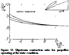
3) At zero velocity and low forward speeds the slipstream contracts between.816 and.92 depending on the loading and the forward velocity, figure 13, (6,a).
4) The slipstream contraction takes place very close to the propeller disk as illustrated on figure 13.
5) Because of the rapid contraction of the propeller slipstream the average axial velocity in the final wake is used for determining wake effects using equation
v = T/m = T/Sp p Vі
where Sp is the propeller disk area and Vі is the axial velocity through the disk.
11) As a result of the lift produced by a propeller when operating at an angle of attack the slipstream is deflected downward, thus reducing the horizontal tail effectiveness.
|
Figure 14. Variation of dynamic pressure in the slipstream of a propeller at Tc = -.1 to 1.2. (Abring, Pressure Distribution, ZWB FD 1908 (1942). ZWB |
Propeller Slipstream – Thrust Effects. Although the actual characteristics of the propeller slipstream are complex it is generally permissible to assume a uniform increase in the dynamic pressure for finding its effects on the airplane. Thus the dynamic pressure in the slipstream q” is
q” = q + T/S p (10)
where Sp is the area of the propeller disk = D /4.
For evaluating the propeller wing combination non – dimensional thrust coefficients based on the stream dynamic pressure are preferred. These coefficients are based on conditions in the free stream and in the slipstream. Thus
Tc = T/q S p (11)
Tc = T/q”Sp (12)
Where Tc is the propeller thrust coefficient based on the free stream dynamic pressure and the primes indicate the coefficient based on. the dynamic pressure q” in the propeller slipstream. In the test and anlysis of propeller V/STOL aircraft the thrust coefficient Tc* based on the total forces of all propellers, wing area and qis used. Thus
Tc = T’/qs = ^ (13)
where К is the number of propellers and T’ = total thrust force.
Lift Due to Slipstream. When wing is immersed in the propeller slipstream an increase lift will be obtained due to the increased q. If the angle of attack is well below that for stall and the effect of the rotational velocity change is small, the lift coefficient can be described in terms of the thrust coefficient and section data by the equation
CL =(4 /о-T") (14)
Thus, the actual lift coefficient based on free stream conditions is increased over the section data.
For the analysis of V/STOL airplanes it is more convenient to use the total wing area and number of propellers in developing the overall performance characteristics.
CL = C " ‘(1 + Tc S/K Sp) (15)
where К is the number of propellers.
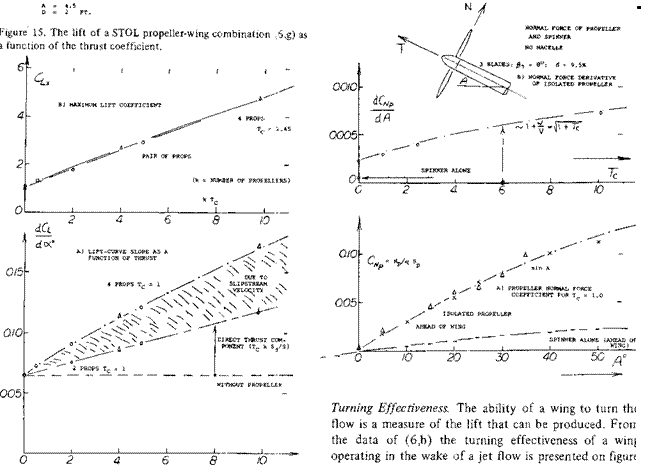
Propeller Wing Lift. The combined lift of a tractor propeller wing combination is higher than the sum of each component alone. The wing lift is increased by the increment of slipstream velocity of the propeller, equation 10, while the lift component of the propeller normal force is increased due to the increase of upwash angle of the wing. In addition to increasing the dynamic pressure at the wing the propeller alters the angle of attack and decreases the lift slope (6,b). An example of the combined lift of the propeller wing combination is given on figure 15 as a function of К Tc. Here, К is the number of the propellers on the wing and Tc is equal to T/q Sp. Note the slope of the lift curve increases due to the direct lift effect and the velocity increase of the slipstream. The maximum lift of the combination depends only on К Tc .
On figure 15 the normal force coefficient and its slope are given for the propeller alone without the nacelle used with the wing. Note the relatively straight line variation of CNp with angle of attack for this case.
Propeller Jet Effect on Wing Lift. When the wing is operating in the propeller slipstream the effective angle of attack is changed along with the lift curve slope. Thus, to calculate the combined lift of the propeller wing combination it is necessary to determine the effect of the propeller jet on the wing, in addition to the propeller normal force and the increase dynamic pressure (6,b).
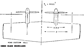
If only one propeller is operating in front of a wing panel the effective jet aspect ratio is one. However, if two or more propellers are used, the jet aspect ratio is found from the equation 16 assuming the spacing is close enough so that the jet is continuous
Aj = B/H (16)
where В and H are the height and width of the jet.
From the detailed calculations of (6,b) the slope of the lift curve can be found for the wing operating in the wake of the propellers from equation 17 and 18
CWo=CL«7A + 2>/[A + Aj + (2-5/1+A)] (17)
^La/uT
Clrtl/1 + [(С, Ш/С )-1][(1-М)/(1+А^ )
Lo’1 ‘ (18)
where M = V/V,’ the ratio of the free stream velocity to the jet velocity or the velocity in the slipstream aft of the propeller. The subscript 1 represents the case where the
 |
velocity over the wing is the jet velocity and о is the free stream velocity. Thus, equation 18 gives the lift curve slope for the free stream velocity case in terms of the slope when the free stream velocity equals the jet velocity. To find the lift curve slope at д, equation 18 must be used. Note all the values of the slope are based on q in the jet. Based on this the slope decreases as the external flow is reduced.
The drag is also effected by the jet flow on the wing. If r = C0ICLZ then
Го =r, ,76(Aj +eAj)+.53 (19) ru = r, [(r0 /r, ) + [1 + Aj -(r0/r,)]
The above equations are valid for the range of A > ViA 16. For the wing operating at zero forward speed the effectiveness is increased by an increase of the jet aspect ratio and a decrease in wing aspect ratio. Thus the lift of the wing will increase as the jet becomes narrower. This shows the advantage of several small propellers washing the wing rather than one large prop.
Total Wing Propeller Lift. The total wing propeller lift is thus calculated by finding the propeller normal force operating in the upwash produced by the wing, adding the change in the wing lift due to the jet effect of the propeller and its associated slipstream velocity. Good correlation with experimental data have been obtained using this procedure for unflapped wings with the propeller thrust axis nearly parallel to the wing chord line. When flaps are used the accuracy correlation is reduced but a good first approximation is obtained.


