Lifetime Experiments
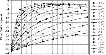
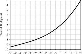
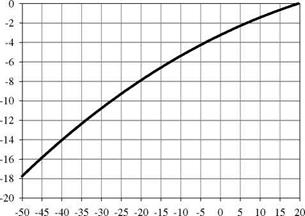
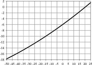
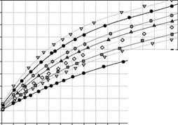
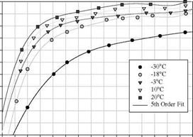
Lachendro (2000) used a set-up shown in Fig. A2 in Appendix A for phase calibration of PSP and TSP formulations at temperatures lower than -30°C, which was capable of holding pressures down to 0.03 psi. In order to make phase calibrations, LED arrays were used as a modulated excitation source; a blue LED array was used for Ruthenium-based complexes and a green LED array for Porphyrin-based luminophores. Each array consisted of seven LEDs arranged in a hexagonal formation for more uniform illumination. The light from an LED array was passed through an appropriate interference filter to eliminate unwanted emission. A function generator was used to directly power and modulate the arrays; the TTL signal from the function generator was used as an external reference for a lock-in amplifier. After passing through a focusing lens, the luminescent response of PSP (or TSP) was detected using a PMT fitted with an interference filter centered at 620 nm and then was sampled by the lock-in amplifier. A PC was used to acquire calibration data from the lock-in amplifier. Figures 6.13-6.15 show phase calibration results for three PSP formulations: Ru(dpp) in a silicone polymer with silica gel, PtTFPP in a silicone polymer with silica gel, and PtTFPP in a porous polymer/ceramic(Al2O3) composite tape casting. Figures 6.16-6.18 show phase calibration results for three TSP formulations: PtTFPP, Ru(trpy)(C6F5-trpy)(NO3)2, and Ru(bipy)2(p-bipy)2 in DuPont
ChromaClear.
и
![]()
 1 -30
1 -30
£
ь -35 -40 -45 -50
0 1 2 3 4 5 6 7 8 9 10 11 12 13 14 15
Pressure (psia)
![]()
 0 -2 -4
|
|
|
|
Temperature (0C) Fig. 6.17. Phase calibration for TSP, Ru(trpy)(C6F5-trpy)(NO3)2 in DuPont ChromaClear. From Lachendro (2000) |
|
Temperature (oC) Fig. 6.18. Phase calibration for TSP, Ru(bipy)2(p-bipy)2 in DuPont ChromaClear. From Lachendro (2000) |
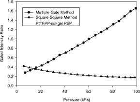
Goss et al. (2000) evaluated the lifetime techniques based on several different modulation/gating combinations such as the time-resolved multiple-gate method for the pulse excitation, sine-square method, and square-square method. The detectors used were ICCD, phase-sensitive interline-transfer CCD, and back-lit CCD with a liquid-crystal shutter. A xenon strobe light and a Nd:YAG laser were used as a pulse light source, while a LED array was used for the sinusoidal and square-wave excitation. PSP tested was PtTFPP in a sol-gel binder. The gated intensity ratio was measured as a function of pressure using the detectors with different gating strategies. They found that the time-resolved multiple-gate method had greater sensitivity to pressure than other lifetime methods and the intensity-based (or radiometric) method. The square-square method had the second best sensitivity to pressure. Figure 6.19 shows calibration results of the gated intensity ratio for that PSP obtained with the ICCD employing the time – resolved multiple-gate method and square-square method. One of the problems with the ICCD was a high noise level of the system; the rms variation of the gated intensity ratio was as high as 3-5% even after binning.
|
Fig. 6.19. Calibration of the gated intensity ratio for PtTFPP-sol-gel PSP with ICCD using the time-resolved multiple-gate method and square-square method. From Goss et al. (2000) |
Bell (2001) studied the time-resolved multiple-gate method for the pulse excitation to optimize the gating parameters. He found that the gated intensity ratio was not constant over a PSP-coated surface even at constant pressure and temperature, and the variation was 0.5-3% depending on homogeneity of the paint. This indicated that the lifetime was different at different locations even when pressure and temperature are uniformly invariant over a surface. Earlier, in laser-scanning PSP measurements, Torgerson et al. (1996) observed a variation of about 0.5o in the phase angle (related to the lifetime) across a measurement domain in the flow-off case where pressure and temperature were constant. Similar to Bell’s observation on the gated intensity ratio, the spatial phase pattern was repeatable, dependent on the location. Hartmann et al. (1995) also observed similar results and attributed this phenomenon to microheterogeneity of the polymer environment. The small lifetime or phase variation may not significantly affect PSP measurements at higher Mach numbers, whereas it can introduce a considerable error in low-speed PSP measurements. To correct this intrinsic spatial variation of the lifetime, Torgerson et al. (1996) and Bell (2001) used raw lifetime or phase distributions in the flow-off conditions as a reference, and took a ratio between the wind-on and reference lifetime images (signals). Unfortunately, this correction method defeats to certain degree the original purpose of using the lifetime method to eliminate the wind-off reference. Bencic (2001) compared the lifetime method with the intensity-based method for PSP measurements at high viewing polar angles and in a shadowed region, and found that the lifetime-based measurements achieved better results in these cases.
Mitsuo et al. (2002) studied the luminescent decay of a PtTFPP-based PSP using a streak camera and found that the multiple-exponential decay of the paint was sensitively dependent on pressure and temperature. This characteristic allowed simultaneous determination of pressure and temperature from three gated intensities obtained by an ICCD camera since two ratios between the three gated intensities had sufficiently different dependencies on pressure and temperature. They selected the first and third gating intervals A T1 = 0 -0.8 |j. s and AT3 = 30-82.8 |J. s. The gated intensity I1 in AT1 was almost independent from both pressure and temperature, whereas the gated intensity I3 in AT3 was very sensitive to pressure and temperature. The second gating interval A T2 = 12 -19.4 |j. s was chosen based on minimization of the pressure error due to a small pertubation of the intensity ratio signal. Their calibration experiments showed that pressure could be well described by polynomials of the gated intensity ratios I1/I2 and I1/I3 with the temperature-dependent coefficients. Using the calibration relations, they were able to obtain simultaneously the surface pressure and temperature fields in a sonic impinging jet from the two gated intensity ratio images. Recent tests by Watkins et al. (2003) used a new internally gated interline transfer CCD camera to alleviate noise sources associated with ICCD.


