Pure Plunging Oscillations
Consider now a harmonic plunging motion, such as would be contributed by blade flapping. Here, the forcing is h = hel(0t so that h = io)hel<ot and h = —a>2hel(0t. Substituting into the expression for the lift given by Eq. 8.13 and solving for the lift coefficient gives
Сі = [ 2ттк(і F-G) – rf] ^eicot. (8.29)
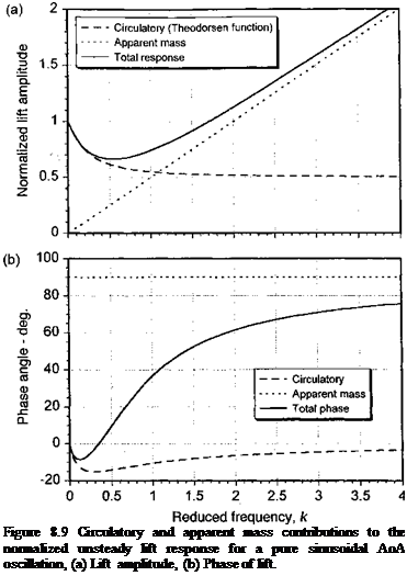
Again, the complete term inside the square brackets can be considered as the lift transfer function. Notice that for this problem the circulatory part of the lift response leads the forcing displacement h by a phase angle of ж/2. Also, the apparent mass force leads the circulatory part of the response by a phase angle of ж/2 or the forcing by a phase angle of ж. The corresponding pitching moment about mid-chord for this case is
![]()
 |
C
mi’2 – f 4 )K ь
|
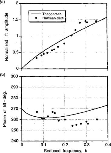
Figure 8.10 Theodorsen’s theory compared to measurements of first harmonic unsteady lift for an airfoil oscillating in plunge, (a) Lift amplitude, (b) Phase of lift. |
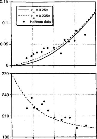
A comparison of Theodorsen’s result with experimental data for an airfoil oscillating in plunge is shown in Figs. 8.10 and 8.11. The results are plotted as a the first harmonic normalized amplitude of the lift and pitching moment about the 1/4-chord and their corresponding phase angles as functions of reduced frequency. The experimental results are taken from Halfman (1951), where measurements were made on an oscillating NAC A 0012 airfoil. These tests were conducted for Mach numbers less than 0.1 and a Reynolds number of approximately 106. It is significant, however, that a relatively high reduced frequency of 0.4 was attained in the experiment. Figure 8.10 shows that there is good agreement between Theodorsen’s theory and Halfman’s measurements. Notice the sign of the lift phase angle, which changes from a lag (less than 270° or minus 90°) to a lead (greater than minus 90°) at higher reduced frequencies as the noncirculatory effects become more dominant. Notice also in Fig. 8.11 that the phase of the pitching moment shows a significant digression from the results obtained with the baseline Theodorsen theory, which predicts a phase lag of 180°. However, this behavior can be explained by the fact that the aerodynamic center
![]()
|
|
|
|
|
|
|
|
|
|
|
|
|
![]()

![]()
location is not at the 1 /4-chord; the results in this case suggest an aerodynamic center for this airfoil and test conditions that is located at 23.5% chord.


