ROTORCRAFT DYNAMICS
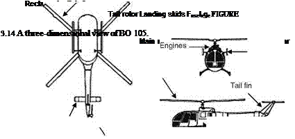
Unlike the fixed-wing aircraft, the lift propulsion and control in helicopters are provided by the main rotor (Figure 3.14). Helicopters have the ability to take off vertically, hover, and land even on unprepared terrain. In a helicopter, the upward lift is obtained by keeping the rotor shaft vertical. The main rotor system of the helicopter should be regarded as a lift-generating mechanism like the wings of an aircraft. The rotors/airfoils produce the lift. The rotor system could be semirigid, rigid, or fully articulated. The engine provides the power to the main rotor and the tail rotor. In a fully articulated rotor, each blade can rotate about the pitch axis that is feathering. This rotation changes the angle of attack and hence the lift. The blade can

move back and forth, that is, lead/lag movement. The blade can also flap up and down. Generally, such a system is used for helicopters with more than two blades. A semirigid rotor has two blades, and when one blade flaps up, the other blade will flap down. There is no lead/lag in this system. The rigid rotor does not provide lead/lag or flapping. Some of this is achieved by the blending of the blades.
Helicopters are inherently unstable and hence small movements of the control inputs are required.
Pedals: Pedals in helicopter are like those in an aircraft, and they can be operated to change the pitch in the tail rotor. The tail rotor is used to counteract the torque effects on the airframe by the main rotor. The pedals are not used to coordinate the turn. The pedals are used to trim the aircraft. The right and left pedals are for yawing to the right and left, respectively.
Collective and throttle: The collective lever increases the pitch in the main rotor collectively. You can raise the collective in the hover condition to gain altitude. The throttle also rotates backward. The collective control thus enables the power change and vertical motion. It controls the pitch of all the blades of the rotor collectively.
Cyclic: This is used for changing the position in hover or forward flight. If the rotor disk is tilted forward with the cyclic control, the outcome is a forward motion. If the cyclic stick is pulled backward, rearward motion is generated. Thus, the cyclic stick enables turn maneuvers and forward movements. It also provides for change in roll and pitch attitude.
To achieve forward or backward motion, the shaft is tilted in the desirable direction. To maneuver, the rotor plane is tilted relative to the horizontal plane to generate the necessary moments. During descent, the flow on the main rotor is reversed and lift is produced even when the engine is turned off. This phenomenon of autorotation can be used to make landings with a failed engine. To fly a helicopter, four types of controls are used. The vertical control is achieved by increasing or
decreasing the pitch angle of the rotor blades. This increases or reduces the thrust, thus changing the altitude of the helicopter. In a single main rotor helicopter, by changing the thrust at the tail rotor, a yawing moment is created about the vertical axis, which is used to provide the directional control. The longitudinal and lateral controls are applied by tilting the main rotor thrust vector. The helicopter would also employ autopilots, fly-by-wire controls, and couple controls.
When talking about rotorcraft dynamics, it is necessary to mention the momentum theory and the blade-element theory. While the momentum theory provides a basic understanding of the flow through the main rotor and the power required to produce thrust to lift the helicopter, it cannot be used alone to design the rotor blades. The blade-element theory looks into the details of how the thrust is produced by the rotating blades and relates the rotor performance to design parameters. The momentum theory for a rotorcraft in hovering condition is discussed next.


