Swept wings of finite span
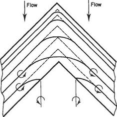
The yawed wing of infinite span gives an indication of the flow over part of a swept wing, provided it has a reasonably high aspect ratio. But, as with unswept wings, three-dimensional effects dominate near the wing-tips. In addition, unlike straight wings, for swept wings three-dimensional effects predominate in the mid-span region. This has highly significant consequences for the aerodynamic characteristics of swept wings and can be demonstrated in the following way. Suppose that the simple liftingline model shown in Fig. 5.26, were adapted for a swept wing by merely making a kink in the bound vortex at the mid-span position. This approach is illustrated by the broken lines in Fig. 5.37. There is, however, a crucial difference between straight and kinked bound-vortex lines. For the former there is no self-induced velocity or downwash, whereas for the latter there is, as is readily apparent from Eqn (5.7). Moreover, this self-induced downwash approaches infinity near the kink at midspan. Large induced velocities imply a significant loss in lift.
|
|
Fig. 5.37 Vortex sheet model for a swept wing
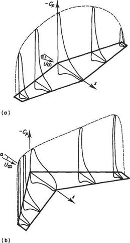
Nature does not tolerate infinite velocities and a more realistic vortex-sheet model is also shown in Fig. 5.37 (full lines). It is evident from this figure that the assumptions leading to Eqn (5.32) cannot be made in the mid-span region even for high aspect ratios. Thus for swept wings simplified vortex-sheet models are inadmissible and the complete expression Eqn (5.31) must be used to evaluate the induced velocity. The bound-vortex lines must change direction and curve round smoothly in the mid-span region. Some may even turn back into trailing vortices before reaching mid-span. All this is likely to occur within about one chord from the midspan. Further away conditions approximate those for an infinite-span yawed wing. In effect, the flow in the mid-span region is more like that for a wing of low aspect ratio. Accordingly, the generation of lift will be considerably impaired in that region. This effect is evident in the comparison of pressure coefficient distributions over straight and swept wings shown in Fig. 5.38. The reduction in peak pressure over the mid-span region is shown to be very pronounced.
|
Fig. 5.38 A comparison between the pressure distributions over straight and swept-back wings |
The pressure variation depicted in Fig. 5.38b has important consequences. First, if it is borne in mind that suction pressure is plotted in Fig. 5.38, it can be seen that there is a pronounced positive pressure gradient outward along the wing. This tends to promote flow in the direction of the wing-tips which is highly undesirable. Secondly, since the pressure distributions near the wing-tips are much peakier than those further inboard, flow separation leading to wing stall tends to occur first near the wing-tips. For straight wings, on the other hand, the opposite situation prevails and stall usually first occurs near the wing root – a much safer state of affairs. The difficulties briefly described above make the design of swept wings a considerably more challenging affair compared to that of straight wings.


