THE a DERIVATIVES (CL„ Стл> QJ
The a derivatives owe their existence to the fact that the pressure distribution on a wing or tail does not adjust itself instantaneously to its equilibrium value when the angle of attack is suddenly changed. The calculation of this effect, or its measurement, involves unsteady flow. In this respect, the oc derivatives are very different from those discussed previously, which can all be determined on the basis of steady-state aerodynamics.
CONTRIBUTIONS OF A WING
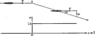
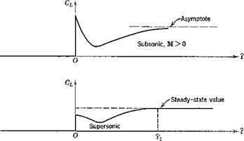
Consider a wing in horizontal flight at zero a. Let it be subjected to а downward impulse, so that it suddenly acquires a constant downward velocity component. Then, as shown in Fig. 7.17, its angle of attack undergoes a step increase. The lift then responds in a transient manner (the indicial response) the form of which depends on whether M is greater or less than 1.
|
|
|
|
|
Fig. 7.17 Lift response to step change in a. (After Tobak, N АСА Sept. 1188.) |
In subsonic flight, the vortices which the wing leaves behind it can influence it at all future times, so that the steady state is approached only asymptotically. In supersonic flight, the upstream traveling disturbances move more slowly than the wing, so that it outstrips the disturbance field of the initial impulse in a finite time tv From that time on the lift remains constant.
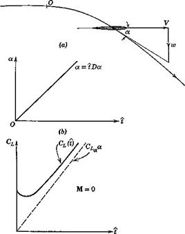
In order to find the lift associated with a, let us consider the motion of an airfoil with a small constant a, but with q = 0. The motion, and the angle of attack, are shown in Fig. 7.18. The method used follows that introduced by Tobak (ref. 7.12). We assume that the differential equation which relates CL(t) with a(t) is linear. Hence the method of superposition may be used to derive the response to a linear a(t). Let the admittance be A(t). Then, [cf. (5.11,2)], the lift coefficient at time і is
CL(і) = f A{i — r)a'(r) dr
Jt=0
Since oc'(t) = Dol — constant, then
The ultimate CL response to a unit-step a input is CL. Let the lift defect be/(f): i. e.
A(i) = CLx -f(t)
Then (7.10,1) becomes
![]() — GT a — 8 Da.
— GT a — 8 Da.
J-‘Ct
where S(i) = ji=af(t — r) dr. The term 8 Da is shown on Fig. 7.18. Now, if the idea of representing the lift by means of aerodynamic derivatives is to be valid, we must be able to write, for the motion in question,
GL(t) = CLa(t) + GLDa (7.10,3)
where CL and CL& are constants. Comparing (7.10,2 and 3), we find that CL± = —S(i), a function of time. Hence, during the initial part of the motion, as already pointed out in Sec. 5.11 the derivative concept is invalid. However, for all finite wings,/ the area S(t) converges to a finite value as t increases indefinitely. In fact, for supersonic wings, 8 reaches its limiting value in a finite time, as is evident from Fig. 7.17. Thus (7.10,3) is valid,/ with constant
f For two-dimensional incompressible flow, the area S(t) diverges as t —>• со. That is, the derivative concept is definitely not applicable to that case.
X Exactly for supersonic wings, and approximately for subsonic wings.
|
|
|
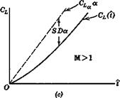
Fig. 7.18 Lift associated with a. |
CL, for values of і greater than a certain minimum. This minimum is not large, being the time required for the wing to travel a few chord lengths. In the time range where 8 is constant, or differs only infinitesimally from its asymptotic value, the CL(i) curve of Fig. 7.18c is parallel to CLga.. A similar situation exists with respect to Cm and Ghe-
We see from Fig. 7.18 that CL., which is the lim — 8(t) can be positive for M = 0 and negative for larger values of M. ^°°
There is a second useful approach to the <x derivatives, and that is via consideration of oscillating wings. This method has been widely used experimentally, and extensive treatments of wings in oscillatory motion are available in the literature,’]’ primarily in relation to flutter problems. Because of the time lag previously noted, the amplitude and phase of the oscillatory lift will be different from the quasisteady values. Let us represent the periodic angle of attack and lift coefficient by the complex numbers
a = a0eim* and CL = CLeimt (7-10,4)
where a0 is the amplitude (real) of a, and CL is a complex number such that |(7io| is the amplitude of the CL response, and arg CLo is its phase angle. The relation between CLo and a0 appropriate to the low frequencies characteristic
Im
Л£со“о
 Fig. 7.19 Vector diagram of lift response to oscillatory a.
of dynamic stabihty is illustrated in Fig. 7.19. In terms of these vectors, we may derive the value of CL& as follows. The a vector is
a = *coa0eJ“‘
Thus CL may be expressed as
Gl = ЩСъУ* + H[CLyat
![]() n[CLo-+i[cLo
n[CLo-+i[cLo
a0
„ dCr I[CT ]
Hence cT =———— — = L° (7.10,5)
d(dc/2 V) kct0
or, if the amplitude a0 is unity, CL& = I[CLo]lk, where к is the reduced frequency tuc/2 V.
To assist in forming a physical picture of the behavior of a wing under these conditions, we give here the results for a two-dimensional;!: airfoil in
f See bibliography.
J Hodden and Giesing (ref. 7.15) have extended and generalized this method. In particular they give results for finite wings.
|
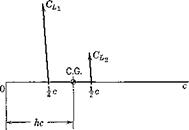
incompressible flow. The motion of the airfoil is a plunging oscillation; i. e. it is like that shown in Fig. 7.11», except that the flight path is a sine wave. The instantaneous lift on the airfoil is given in two parts (see Fig. 7.20):
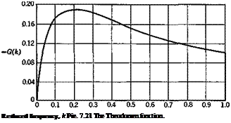
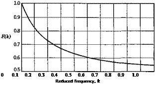
and F(Jc) and G(k) are the real and imaginary parts of the Theodorsen function C(k), plotted in Fig. 7.21. The lift that acts at the midchord is proportional to a = z/F, where z is the translation (vertically downward) of the airfoil. That is, it represents a force opposing the downward acceleration of the airfoil. This force is exactly that which is required to impart an acceleration z to a mass of air contained in a cylinder, the diameter of which equals the chord c. This is known as the “apparent additional mass.” It is as though the mass of the airfoil were increased by this amount. Except in cases of very low relative density /л = 2mjpSc, this added mass is small compared to that of the airplane itself, and hence the force CLi is relatively unimportant. Physically, the origin of this force is in the reaction of the air which is associated with its downward acceleration. The other component, , which acts at the } chord point, is associated with the circulation around the airfoil, and is a consequence of the imposition of the Kutta-Joukowski condition at the trailing edge. It is seen that it contains one term proportional to « and another proportional to a. From Fig. 7.19, the pitching-moment coefficient about the C. G. is obtained as
 |
From (7.10,6 and 7), the following derivatives are found for frequency 1c.
= 2 rrF(k)
![]() CL = 77 + 2t7
CL = 77 + 2t7
![]()
 |
Gma = 2nF(k)(h – i)
Gmsc = 77(h – x) + 2,7^ (h – i)
The awkward situation is evident, from (7.10,8), that the derivatives are frequency-dependent. That is, in free oscillations one does not know the value of the derivative until the solution to the motion (i. e. the frequency) is known. In cases of forced oscillations at a given frequency, this difficulty is not present.
When dealing with the rigid-body motions of flight vehicles, the characteristic nondimensional frequencies к are usually small, к < < 1. Hence it is
reasonable to use the F(k) and G(k) corresponding to к —»- 0. For the twodimensional incompressible case described above, lim F(k) = 1, so that
CL = 2tt and Gma — 2n(h — J), the theoretical steady-flow values. This conclusion, that CL^ and Cm^ are the quasistatic values, also holds for finite wings at all Mach numbers. The results for CL and Gm& are not so clear, however, since lim G(k)jk given above is infinite. This singularity is marked for the example of two-dimensional flow given above, but is not evident for finite wings at moderate aspect ratio. Miles (refs. 7.13, 7.14) indicates that the к log к term responsible for the singularity is not significant for aspect ratios less than 10, and the numerical calculations of Rodden and Giesing (ref. 7.15) show no difficulty at values of к as low as.001. Filotas’ (ref. 7.16) more recent solutions for finite wings bear out Miles’ contention. Thus for finite wings definite values of and Cm^ can be associated with small but nonvanishing values of k. If the airfoil has a control flap, the hinge moment associated with a, , behaves like CL& and Gm . The limiting values described above can be obtained from a first-order-in-frequency analysis of an oscillating wing. To summarize, the a. derivatives of a wing alone may be computed from the indicial responses of lift, pitching moment, and hinge moment, or from first-order-in-frequency analysis of harmonically plunging wings.


