The helicopter
In a true helicopter in normal flight, the upward thrust of the revolving blades must be equal to the weight; forward motion is produced by inclining the effective axis of the rotor forward which normally entails tilting the nose of the helicopter down. The actual means by which this is achieved is rather complicated and involves altering the cyclic variations in rotor blade incidence. Owing to the reaction of the torque of the lifting blades the whole aircraft will try to rotate in the opposite direction, this resulting in a tendency to yaw which corresponds to the rolling tendency due to the propeller on a fixed-wing aircraft. The yawing tendency can be counteracted either by an auxiliary propeller or by a jet reaction system at the tail; this can also be used to provide directional control and to save the necessity of having a rudder (Fig. 6D).
The development of successful helicopters has involved the solution of many other practical problems. The blade going into the wind (the wind produced by the motion of the aircraft) gets more lift, and drag, than the blade going down wind. This happens whenever the machine moves in any direction, forwards, backwards or sideways; but it becomes an even more serious problem when moving at high speeds because the tip portions of the blade going into the wind meet compressibility problems before the aircraft itself is moving anywhere near the speed of sound; this fact has so far limited the speed of helicopters to something like 200 knots (370km/h). The helicopter has other failings too, vibration is apt to be excessive, as is the noise when compared with aircraft of similar power.
Attempts to solve these and other problems have resulted in wings that must not only rotate, but also have cyclically and collectively variable incidence, hinges to give variable dihedral (resulting in a kind of flapping motion of the blades), drag hinges to allow the blades to bend backwards, and sometimes, a tilting axes of rotation. Then there are the auxiliary propellers at the tail, or jets, some have had jets too at the wing tips to rotate the blades, some have had more than one set of rotating wings (like contra-rotating propellers), and there have been many other ingenious devices, all helping to some extent to solve the problems, but all contributing to the complication and weight of an already complicated type of aircraft.
Recent developments have included the use of so-called ‘rigid’ rotors, where the flapping and drag hinges are replaced by flexures. This has reduced the mechanical complexity, and also the weight of the rotor head. Another development has been the shrouding of the tail rotor in a kind of fin. This results in less drag and reduces the possibility of accidental contact with the tail rotor. A further development has been the replacement of the tail rotor with a variable air jet at the rear to perform the same function. This type, known as a NOTAR, (standing for No Tail Rotor) is much quieter than the conventional helicopter, and also avoids the possibility of damage to or from the tail rotor.
The main limitation of a conventional helicopter remains its low maximum speed. One of the reasons for this is that in order to generate lift, a significant
|
|
|
|
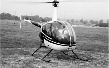
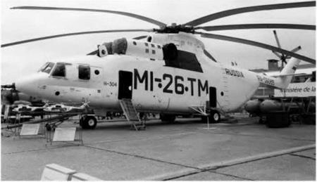
Fig 6D VTOL – helicopters
Top: The tiny but popular Robinson R-22, with piston engine and rubber belt drive. Flying it feels like trying to ride a monocycle at first.
Bottom: At the other extreme, the massive Russian Mil Mi-26 TM capable of lifting a load of 196 000 newtons (20 tonnes).
part of the retreating blades must be going faster than the relative air speed past the helicopter. This means that the advancing ones will be going more than twice as fast as the aircraft, and will therefore go supersonic when the aircraft is still flying at significantly less that half the speed of sound. Several solutions have been proposed and even developed. One of these is the so-called ‘compound’ helicopter. This has the normal features of a conventional helicopter but also has small wings and a separate engine or engines to provide forward thrust directly. At high speed, the wings provide most of the lift, allowing the rotor to be rotated relatively slowly or even be feathered. A number of examples have been built, but so far it remains something of a rarity. A possible alternative is provided by development of the coaxial rotor helicopter which has two contra-rotating rotors mounted on the same shaft or sometimes two close shafts with intermeshing rotors. On this arrangement, it is possible to arrange for the lift to be generated primarily by the advancing blades of the rotors, the retreating blades providing little or no lift. Since they do not have to provide lift, the retreating blades can be feathered and do not need to go faster than the relative flow speed past the aircraft. This of course means that that the advancing blade can be going correspondingly slowly. Many practical examples of coaxial rotor helicopters have been manufactured and they are not uncommon, particularly in military applications. They have the added advantage that no tail rotor is required. Their disadvantage lies in the extreme complexity of the rotor head, and the problems caused by intersecting rotor wakes. As yet, the potential of the coaxial rotor for very high speed flight has not yet been realised on production examples.
Jet lift
Until recently, the only serious contenders to the helicopter have been jet lift and thrust vectoring aircraft, and the only really successful one was the Harrier, (known as the AV-8 in the USA). The Harrier (Fig. 6G, later) uses downward deflection of the engine to produce a lifting thrust until sufficient forward speed has been obtained for the wings to take over the job of lifting. The engine outlet nozzles, two from the hot exhaust and two from the compressor, can be ‘vectored’ (varied in outlet angle) from vertical or even slightly forward, to horizontal in order to obtain the desired balance between lift and forward thrust. The thorny problem of providing stability and control at low speed is solved by using four ‘puffer’ jets of compressed air bled from the engine. These are situated at the nose, the tail and both wing tips. Tike the helicopter, this aircraft can be flown backwards forwards and sideways. It can also hover and land and take off vertically. Although it is capable of vertical take-off, it is more economical in terms of fuel burn for the aircraft to make a short horizontal take-off, with the engines set at an intermediate angle so as to provide thrust and some lift. It may therefore be classified as V/STOT, meaning that it can use vertical and short take-off.
During the cold war, the Soviet Union developed a rival to the Harrier, the Yakovlev Yak-36. This aircraft used an alternative method of jet lift in that it employed separate engines for lift instead of just relying on thrust vectoring. For many years, however, the Harrier was the only really practical jet lift aircraft in service anywhere, but after much political indecision and argument, the Lockheed Martin F-35 JSF (Joint Strike Fighter) finally emerged. Some variants of this have similar V/STOL capabilities to the Harrier, and a much higher top speed. Thrust vectoring is used, but in addition, a fan driven by the engine provides part of the lift.


