Viscous dissipation relations
In Section 4.5.4, viscous dissipation was shown to be ultimately responsible for total profile drag, including the pressure drag component. Since dissipation is therefore a key quantity to be minimized, it’s useful to examine how the dissipation coefficient cD depends on the other boundary layer parameters. For self-similar laminar flow, this dependence is given by Table 4.1. For self-similar turbulent flow, it can be obtained from the kinetic energy shape parameter equation (4.98) together with the G-beta locus (4.58) as follows.
|
dff* ds |
Since turbulent equilibrium flows have a streamwise-constant G, they must have a very nearly constant H and hence also a constant H* if we neglect the slight streamwise variation of the turbulent Jcf /2 factor in the G definition (4.56).
|
я* Гс/ / H-1 1 ҐН-13 ~2 ~2~ BH ) + ~Ш H ) |
We can now obtain an expression for equilibrium-flow cD from (4.98) by dropping the dH*/ds term and eliminating в/ие due/ds using the G-beta locus (4.94). The H** term is also dropped since this is typically small, and is exactly zero in incompressible flow.
 |
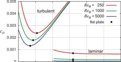
Aside from additional minor non-equilibrium corrections, expression (4.100) is in fact used in two-equation methods as a closure function for cD in the ODE (4.98) to enable its integration. It is shown in Figure 4.25 for several momentum thickness Reynolds numbers. Also overlaid is the laminar cD(H, Bne) function for the laminar Falkner-Skan flows, tabulated in Table 4.1. The turbulent cD is seen to have a fairly weak dependence on Req, while the laminar cD ~ 1 /Bee dependence is much stronger.
1 1.5 2 2.5 3 3.5 4
H
Figure 4.25: Dissipation coefficient for self-similar flows. Laminar values are listed in Table 4.1. Turbulent values are given by equation (4.100). Weak pressure gradients which displace H slightly from the flat plate value have little effect on cD.
For any given local Bee, the minimum dissipation occurs very close to the zero pressure gradient (flat-plate) H value, so that the dissipation is relatively insensitive to small changes in H, i. e. to weak favorable or adverse pressure gradients. The laminar cD is also very nearly independent of pressure gradient.
The weak dependence of cD on pressure gradients (assuming fixed transition locations) indicates that the dissipation V{s) = peJ cv is primarily determined by the cube of the edge velocity And since the integrated D(s) distribution gives the profile drag via expression (4.49), airfoils which have strong “overspeeds” or regions of high velocity are expected to have large integrated dissipation and high drag. Conversely, low drag is likely to be achieved by airfoils which have more uniform velocity distributions.
Note that since expression (4.49) captures the sum of friction and pressure drags, this argument applies to both the friction and pressure drag components. Attempting to reduce the pressure drag “directly,” for example by reducing pressures on front-facing surfaces and increasing pressures on aft-facing surfaces, is bound to be futile if viscous dissipation is not reduced in the process.
|
2cd IT* |
Another important role of the dissipation coefficient is that it controls the maximum tolerable adverse pressure gradient which a boundary layer can sustain with a constant margin from separation, or equivalently with a nearly constant H and H*. In this situation the shape parameter equation (4.98) with dH*/ds = 0 can be viewed as an equation for the most negative tolerable velocity gradient.
The second approximate value in (4.101) is valid for turbulent flow in very strong adverse pressure gradients near separation where H~3, H* ~ 1.5, and Cf is relatively negligible.
One implication of (4.101) is that the adverse pressure gradient capability of the boundary layer can be increased by increasing its dissipation, preferably away from the surface so that the offsetting Cf term in (4.101) is not increased as much. One common technique is by the use of vortex generators [27], which
increase dissipation by introducing streamwise vortices into the boundary layer at some distance from the wall.


