Effect of Different Helicopter Configurations on the Required Power
Three principle configurations of helicopters to date have found extensive use: the single rotor with anti-torque tail rotor, the tandem configuration, and the intermeshing rotors. Each configuration has something to recommend it and, conversely, its adverse points; for example, the single-rotor configuration is more critical than the tandem configuration from the standpoint of loading because of the limited eg travel of the single rotor. On the other hand, the tandem-rotor configuration requires more induced power than the single-rotor because of the lower “aspect ratio” of the tandem helicopter. The relative merits of the tandem – and single-rotor helicopters are adequately covered in Refs. 14 and 15, and are not dwelt on here. Instead, problems in calculating the required power, specific to each configuration, are presented.
Single Rotor. In addition to the power required by the main rotor, the single-rotor configuration requires power for the tail rotor to overcome the torque of the main rotor. The power required by the tail rotor can be calculated in the same manner. If lT is the distance from the eg to the tail rotor, then
lTTT — Q,
where Q = main rotor torque,
TT = tail rotor thrust.
In coefficient form this becomes
r _____ ________ ZL_______
TT (lT/R)(AT/A)(VTT/VTf
where AT = tail rotor area,
Vtt = tail rotor tip speed.
 |
Consider the example helicopter once again. Let
From the 736 hp calculated so far CP for the main rotor is 49.5 x 10 5 Thus
CTt = 16(49.5 x 10“5) = 79.1 x 10"4,
— 6CT _ Z—Lr,
![]() CLT ~
CLT ~
so that
aT — 0.095.
The induced power would be approximately
C2
Cp = = 1.01 X 10"
2fi
The profile power is given approximately by C
The total power coefficient of the tail rotor is therefore CPt = 2.10 x 10 4. The corresponding tail rotor power is 20.2 hp or 2.8% of the main rotor
|
Fig. 5-25. Downwash for rotors of tandem helicopter. |
power. This agrees fairly well with the percentage usually quoted for singlerotor helicopters. The tail rotor power of a single-rotor helicopter is usually of the order of 5% of the main rotor power.
Tandem-Rotor Helicopter. The tandem-rotor configuration in Fig. 5-25 does not require an antitorque tail rotor, for the main rotors rotate in opposite directions in which the torques cancel. Although this would appear to be power-saving, the tandem configuration suffers an increase in the induced power because the rear rotor operates in the downwash of the front rotor. This might be reasoned intuitively by comparison with a fixed wing; that is, the induced “drag” of a tandem helicopter for the same disk loading is higher than a single-rotor helicopter because of the lower aspect ratio of the tandem.
Although it is admittedly crude, the present method of calculating the power required by a tandem helicopter assumes that the rear rotor operates in an additional uniform downwash induced by the forward rotor. Consider Fig. 5-25.
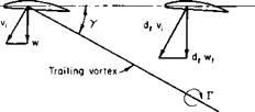
If wf is the downwash of the forward rotor, the rear rotor acts under the influence of its own induced downwash, wa, plus the dfwf of the forward rotor. The factor df must vary between zero and 2 as the helicopter transists from hover to forward flight. For nonoverlapped rotors the interference between the rotors is negligible in hover. Actually, Ref. 16 discusses the possibility of a slight favorable interference in hover, possibly the result of an upwash induced into each rotor by the other. Obviously, from momentum or vortex considerations, the value of df cannot be any greater than 2. The
|
i
|
|
Fig. 5-26. Trailing vortex from tandem wing.
|
actual variation of df with forward speed is difficult to determine, for it would be expected to vary with the geometry of the helicopter—specifically with the position of the rear rotor in relation to the forward one and with the ratio of the downwash to the forward velocity, for this ratio determines the angle at which the trailing vortex system is shed from the forward rotor.
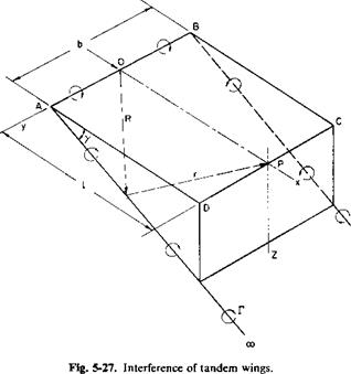
An approximate idea of how df varies, at least for nonoverlapped rotors, can be gained by applying the analogy of two wings in tandem (see Fig. 5-26).
 |
Consider only a simple horseshoe vortex and calculate the ratio of the downwash induced at the center of the second wing to that induced at the center of the first. To do this, the Biot-Savart law can be applied to Fig. 5-27. A and В are the tips of the first wing and О is the midpoint; D, C, and P are the corresponding points on the second wing. The velocity in the Z-direction induced at P is
But
and
ds = dR
і dx + к tan у dx.
Substitution of these relationships and performance of the indicated integration results in
where
 |
For
Hence
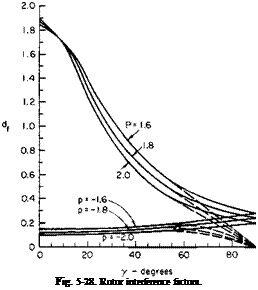
Equation (5-52) is presented graphically in Fig. 5-28. Observe that df approaches 2 as у approaches 0 and l becomes infinite. For у = п/2, df has
 |
the value of 1/(1 + p2). The assumed model is questionable for y-values near 90°. Such values would correspond to overlapped rotors in hovering, and the results of Eqs. (5-11) and (5-12) should be used. Negative /?-values correspond to the influence of the aft rotor on the forward one. This effect is normally neglected for tandem rotors, but we can see that it may be significant for certain operating conditions.
The angle у is a function of V, w, and the trim of the helicopter. For the case in which the helicopter is trimmed level у is calculated approximately from
![]() у = tan
у = tan
![]() 1.57}
1.57}
2 pAfV2 where sub / refers to the forward rotor.
The ratio p is given as the distance between rotors divided by the radius. For tandem helicopters with only a small amount of overlap df varies from approximately 1.5 at 60 knots to about 1.8 at 80 knots and remains fairly constant at higher speeds.
A comparison can be made between a single rotor and a tandem helicopter
 with the same gross weight and disk loading by assuming that the thrust is equally divided between the two rotors of the tandem. According to simple momentum relationships, the induced power in forward flight for an isolated rotor is
T[2] [3]
P, =——–
1 2 pAV
For the aft rotor this becomes
Thus the total P, would be
= (T/A)2T f d;
2 PV V 2
or
P = —— W + —
‘total 2 pV ~
where wd = disk loading.
For a single rotor of the same gross weight and disk loading the induced power would be
of equal payload. Some of this power is also regained, in comparison with the single rotor, because of the absence of a tail rotor.
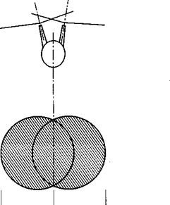
Intermeshing Rotors. The intermeshing rotor configuration is fundamentally the same, as far as the mechanics of the fluid motion is concerned, as the single rotor. However, unlike the coaxial configuration or single rotor, the effective disk area of the intermeshing configuration is slightly noncircular because of the small lateral displacement of the two rotors shown in Fig. 5-29.
|
-«———- ь ———– *- Fig. 5-29. Intermeshing rotor configuration. |
The equations developed for the single rotor can therefore be applied to the configuration with intermeshing rotors. For calculation of the induced power the shaded area in Fig. 5-29 should be used for the disk area. For calculation of the rotor solidity the total solidity of both rotors should be used. The induced power in forward flight should be based on the combined span b.


