FUSELAGE INTERACTION
In all airplanes with a central vertical fin, the fuselage has a considerable influence upon the lateral forces produced on and by the vertical surface.
Aspect Ratio. Modern airplanes usually have vertical tail surfaces with an exposed geometric aspect ratio larger than unity. The lateral or normal forces originating in them, may thus be proportional to the angle of yaw or sideslip. The lateral force characteristics of vertical tails can be from the data such as (5,a) or that of Chapter XVIII. In the statistical evaluation of tested lateral forces (subscript “lat”) we will use equation (12) of Chapter XVIII, for indicating the yaw angle required to produce a certain force in the vertical tail. This equation is:
VdCA6 =10° +(10°/Аг)+19°/Ac (14)
Because of physical continuity between fuselage and tail, it is difficult to determine the effective ratio A^; and the magnitude of the effective lateral area due to the appreciable amount of fuselage interference upon the vertical surface.
(4) Yaw moments due to other appendages:
a) Jaquet, Fuselage with Ducts, NACA TN 3481 (1955).
b) MacLachlan, Influence of Canopies, NACA TN 1052 (1946).
c) External stores or tanks.
(5) Lateral Force on tails
a) Dods, Nine Related Horizontal Tails NACA TN 3497.
Cylindrical Fuselage. In configurations where the fuselage is a body of revolution, a simple geometric definition for finding the span, area and aspect ratio of the vertical tail surface is to use the distance from the tip to the body’s center line. Lateral force characteristics are shown in figure 9 of a rectangular fin attached to a cylindrical “fuselage”. This configuration is basically similar to the combination of a wing with a tip tank. A theory of the interaction is presented in (7); and tip-tank results are evaluated in the Chapter III.
Roughly, the cylinder will have a lift-increasing effect similar to an end plate. The effective aspect ratio is theoretically increased by a maximum of
AA = Av/(d/b); A^ = A ^(1 + d/b) (15)
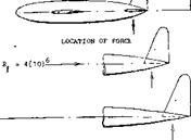
Considering the results in figure 8, the “force angle” of the vertical surfaces tested without the presence of a horizontal surface can be explained by combining equations (14) and (15). For example, for the geometrical aspect ratio A^ = 1.33 (measured to the center line of the fuselage) we obtain a sectional angle d^s/dCj^ := 15.7°, and an included component of 19/1.33 = 14.3 . The combined angle is 30°, and the force derivative is thus dCj^ /dj3 – 0.033. This is much smaller than the tested value (0.043). To account for the end plate effect of the fuselage (d/h = 2/3), the function in figure 15 of the Chapter III can be used. The effective aspect ratio is then found to be A^^ 1.33 (1.5) = 2; and the derivative of the lateral angle required, is expected to be d^/dC= 10 + 2.5 + 9.5 = 22 . The corresponding slope of the lateral force is dC^/d^ = 0.045 which is close to the tested value of 0.043 Part (b) of the illustration shows that a tapering afterbody results in somewhat reduced tail effectiveness.
Fuselage Force. In case (c) of figure 9, another vertical tail surface is attached, not to the end of the fuselage, but somewhere near half of its length. The lateral force due to the tail surface (having an aspect ratio of 2.2) is so high that it cannot adequately be explained in the manner as above. Load distribution tests (6,c) carried out on the last (swept) fin in the illustration, reveal that the combined lateral force, on the fin and induced upon the fuselage by the fin, is about 50% larger than that in the exposed vertical area. It thus seems that presence of the fin converts that part of the fuselage into a piece of “wing”. The vertical tail effectiveness can be explained or predicted, using equations (14) and (15) considering an area producing lateral forces to be effective within the fuselage, equal in magnitude to (d c) as indicated in figure 8. In practical designs it does not seem likely, however, that a tail surface would not be located near the very end of the fuselage (where the moment arm is longest).
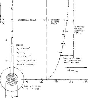
9, may be used in aircraft exhausting the propelling jet through the blunt base. Airplanes with propeller propulsion, generally have fuselages with a more or less tapering tail end. Experimental investigation of several “families” of vertical fins (9) (10) (11) (12) permits evaluation of their effectiveness as a function of the size of the fuselage to which they are added. In one of those (8) the vertical tail aspect ratio varies between 0.5 and 4.0, and its area S^/ between 0.6 and 6.0 of the fuselage’s frontal area S. Results have been transformed to our method of defining vertical dimensions from fuselage center line. Figure 9 demonstrates for the nominal aspect ratio A^ = 2, how the lateral force angle derivative d^/dC^y. = l/CdC^./d^) varies as a function of the tail size ratio hyz/d’^, where dy = diameter of the fuselage at the quarter-chord location of the vertical tail attached to it.
(6) Vertical tails on cylindrical fuselages:
a) Sleeman, Various Configurations, NACA RM L57C08.
b) Wiley, Fin on Cylinder, NACA RM L53J19.
c) Wiley, Swept Fin & Horizontal Tail, NACA RM L55E04.
d) Few, Tails on Boat-Tailed Body, RM L57D22.
(7) Theoretical analysis of fuselage interaction:
a) Hartley, Wings with Tip Tanks, ARC CP 147 (1954).
b) Weber, Wings with Cylinder, ARC RM 2889 (1957).
(8) Michael, V’Tail Fuselage Interference, NACA TN 3135 (1954).
 |
 |
13-8
The results can be interpolated by
й/>Ійсиі =12° + 18АЧ
where = effective aspect ratio of the tail surface, including the end-plate effect of the fuselage:
A^ = 2(l+2(d^/hA)) (16)
Assuming that the maximum diameter of the fuselage might statistically be d = 2 d^ , we readily obtain equation (15). The fuselage’s end-plate effect is thus the reason why the functions in figures 10 and 20 are or should not be straight lines.
Figure 9. Evaluation (8) showing the end-plate effect of the fuselage upon the vertical tail surface.
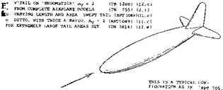
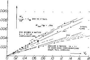
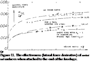
Fuselage Length has an effect different from diameter. In figure 11, we have plotted the lateral force slopes of several series of vertical tail surfaces against the size ratio h/f. The tail effectiveness increased by the end-plate effect of the fuselage is reduced because of presence and growth of the boundary layer along the fuselage. Since the “volume” of the viscous wake at the end of the fuselage is proportional to its length “j(”, the favorable interaction with the vertical surface (fin) is reduced as a function of I /h, or increasing with Ъ. Ц. Of course, when increasing the size of the vertical surface indefinitely, the force derivative should come down again, ending up at the level as for the isolated tail.
(9) Influence of horizontal on vertical tail:
a) Katzoff, End-Plate Effect, NACA TN 797 (1941).
b) Murray, End-Plate Effect, NACA TN 1050 (1946).
c) Brewer, Swept Tail Surfaces, NACA TN 2010 (1950).
d) Rotta, Aerodynamic Characteristics of Wing with End
Plate at One Tip, Ingenieur Archiv 1942 p. 119.
e) Root, Empennage Design, J. Aero. Sci. 1939 p. 353.
f) MacLachlan, Directional Stability, NACA TN 1052 (1946).
g) ![]()

![]()
![]()
![]() Marino, Load Distribution, NACA TN 2488 (1952).
Marino, Load Distribution, NACA TN 2488 (1952).
![]()
![]()
![]()
![]()
![]()

![]()
![]()
![]()
![]()
![]()
![]()
![]()


 0.059 ! (.042)) 1.00
ESTIMATED
0.0090 (.0083) 0.0038 (.0036 —
О
|
|
0.064 (.064) 0.94
:. ee)
V ь
*v у –
VALUES LISTED ARE DIFFERENTIALS DUE TO VERTICAL TAIL
(VALUES) ARE TESTED WITHOUT THE HORIZONTAL SURFACE
Figure 12. Interference of wing and fuselage upon the lateral force and the yaw moment produced by the vertical tail surface.
(10) Lateral investigation of one and the same basic wing – fuselage-tail configuration in NACA wind tunnels:
a) Bamber, I – Several 23012 Wings, TN 703 (1939).
b) Bamber, II – Lateral Characteristics, TN 730 (1939).
c) Recant, III – Component Characteristics, TN 825 (1941).
d) Recant, Side Flow at Tail, TN 804 (1941).
e) Jacobs, 209 Combinations Pitching, Rpt 540 (1935).
f) House, 4 Wings, 2 Fuselages, 2 Fins, Rpt 705 (1941).
(10) g) Fehlner, I – 5 V’Areas, 3 Fuselage Lengths, W’Rpt L-12(1944).
h) Hollingworth, II & III – Same as in (g), W’Rpt L -8 & 17
(1945) .
i) Recant, IV – Wedge-Shaped Fuselage, W’Rpt L-520 (1942).
j) Wallace, V – Tapered Wing, W’Rpt L-459 (1943).
(11) Related wing, fuselage, swept tail model family:
a) Brewer, Lateral Characteristics, TN 2010 (1950).
b) Letko, V’tail Stability Contribution, TN 2175 (1950).
c) Queijo, Size & Length of V’Tail, Rpt 1049 (1951).
d) Lichtenstein, Tail Length and H’Tail, Rpt 1096 (1952).
e) Yawing characteristics of same family, see NACA TN 2358.
f) Longitudinal characteristics, see NACA TN 2381 & 2382.
g) Wolhart, Three Aspect Ratios, TN 3649 (1956).
h) Also references (2,f, h) and (4,a) and (13,f). [120]


