Helicopter Performance
Methods can now be developed for calculating the various performance items of a helicopter:
1. The maximum speed Fmax.
2. Cruising speed.
3. Absolute ceiling.
4. Service ceiling.
5. Forward rate-of-climb.
6. Hover ceiling IGE (in-ground-effect).
7. Hover ceiling OGE (out-of-ground-effect).
8. Fuel consumption.
9. Range.
10. Vertical rate-of-climb.
11. Time-to-climb.
The calculation of these items, except for hover and vertical performance, is similar to the procedure followed for fixed-wing aircraft. The first step in the calculation of the forward flight performance is to determine the power required and the power available as a function of forward speed for various altitudes. The calculation of the power required proceeds according to the methods just presented. The determination of the power available follows from the engine specifications furnished by the engine manufacturer. In addition, however, suitable allowance must be made for the various losses associated with the engine installation in the helicopter:
1. Duct losses.
2. Cooling power.
3. Accessory power.
4. Transmission losses.
Power Required. The required power is the sum of three parts: (1) the induced power, (2) the profile power, and (3) the parasite power. The induced power varies inversely with V at the higher speeds. The parasite power varies directly with the cube of the forward speed, and the profile power increases only slightly with the square of the forward speed over that required in hover. Qualitatively, the power breakdown in forward flight is shown in Fig. 5-30.
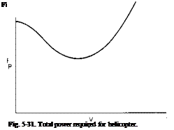
The total power required, therefore, has the form represented in Fig. 5-31.
At the lower speeds the power required decreases with increasing V because of the drop-off in the induced power. However, the parasite power increases with V3 so that the speed reached corresponds to the minimum power required at which an increase in V results in an increase in the parasite power greater than the decrease in the induced power. The value of the velocity, Fopt, corresponding to the minimum power, can be found approximately by writing the power required as
This equation assumes that the variation of the profile power with V is
negligible. By differentiating (5-53) with respect to V and equating it to zero we obtain
or
P = 3 P
x 1 x n
 |
|
Thus it can be seen that at minimum power the induced power is approximately three times the parasite power. This result is identical to that given in many texts for fixed-wing aircraft. Solution of the above equation for V0J)l results in
A little contemplation of (5-54) reveals several interesting facts. First, because most helicopters employ approximately the same disk loading and A/f is a dimensionless geometric ratio that is nearly constant from one helicopter to the next, the speed Vopi for minimum power would be expected to be nearly the same for all helicopters. At sea level Vopt is usually of* the order of 60 to 70 knots. Second, it can be seen that Fopt increases as / decreases, that is, as the aerodynamic cleanliness of the helicopter is improved. Third, Fopt is seen to increase with increasing disk loading. Finally, Vopt increases with increasing altitude as the density decreases. Because the power available for a helicopter is independent of forward speed, it will be shown later that Vopt is the forward speed that results in the best rate of climb.
Parasite Drag. The parasite drag is important to the operation of a helicopter. This statement is somewhat paradoxical in view of the fact that the helicopter is a slow-speed aircraft and that its chief virtue lies in its VTOL capabilities. Nevertheless, the majority of the missions for which helicopters are employed favors the machine with the best range. Army missions are concerned with the radius of action of the helicopter in delivering troops and supplies. Navy missions are concerned with the radius of action in the performance of ASW (antisubmarine warfare) or rescue missions. Commercial operators, of course, are concerned with drag because its reduction results in a corresponding saving in fuel, which, over the year, can represent a considerable expenditure.
Power Available. Power available is defined here as the power supplied directly to the rotors after the various losses have been removed. It excludes power to any antitorque tail rotor, which is considered to be part of the power required. The determination of the power available is obtained by the use of the engine specifications furnished by the manufacturer.
The power from the engine is delivered to the rotors by a system of shafts and transmissions through which certain losses occur. Although a certain amount of the power lost in a transmission is independent of the transmitted power, being more a function of the rpm, it is common practice to assume a percentage loss in the transmitted power. A figure of 1% per gear mesh is representative of this loss.
In addition to the transmission losses, a penalty may be incurred in the power in order to cool the engine. This loss will vary greatly from one installation to another, depending on the cooling system design. To have some appreciation of the magnitude of this loss, it is stated here simply that for one particular installation of which I have knowledge this loss is of the order of 2.5% of the engine power.
Still another loss in the engine power of reciprocating engines is incurred because of the losses in total pressure in the carburetor inlet ducting and increases in the back pressure produced by exhaust stacks and ducts. Again, this loss depends on the design of the particular configuration; in general, however, it is of the order of 1 or 2% of the engine power output. Finally, an increment must be subtracted for the power required by accessories such as the generator or alternators.
Thus the power available to the rotors can be 4 to 8% less than that delivered by the engine or engines.
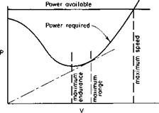
Power Required and Power Available. A typical variation of power required and power available as a function of speed for a given altitude and gross weight is shown in Fig. 5-32.
Of course, there are different definitions of power available, by which is meant, specifically, normal rated power and military power (or takeoff power). Normal rated power is the continuous power rating of the engine and is usually the one of most concern. There are two immediate observations to be made from Fig. 5-32. The first is the maximum forward speed Fmax which is determined by the intersection of the power-available curve with the power-required curve. It is, of course, the power-limited Fmax. It is entirely possible, as already discussed, that the maximum speed may be limited by the onset of retreating blade stall or compressibility effects which produce excessive vibration levels.
The second point to be observed in Fig. 5-32 is the velocity V2 that corresponds to the minimum power required. This forward speed is obviously the best forward speed for maximum endurance, for the rate of fuel consumption in steady flight is proportional to the power required.
Cruising Speed for Maximum Range. The brake specific fuel consumption varies slightly with the brake horsepower. However, for the present, it is assumed that the BSFC is constant. If RHPreq is the required power and rj is the transmission efficiency (including cooling and duct losses), the fuel flow at any forward speed is given by
RHP
lb/hr = (BSFC)—— » (5-55)
Ц
where BSFC = pounds of fuel per brake horsepower hour.
|
Fig. 5-32. Typical power-available and power-required curves. |
The pounds of fuel used per mile is given by
Because BSFC, as well as tj, is assumed to be constant, it can be seen that the pounds of fuel used per mile are a minimum when RHP/F is a minimum. This ratio is the arc sin of the included angle between the F-axis and a line from the origin to the power-required curve. This angle has its maximum value for a line just tangent to the power-required curve. The velocity at this point, given in Fig. 5-32, is the cruising velocity for best range.
This condition for tangency to the power-required curve is modified if the BSFC is not constant, but it depends on the power. In this case the procedure to follow uses Eq. (5-56) to calculate the quantity mi/lb and to plot it as a function of V, as in Fig. 5-33. The velocity that gives the maximum value of the mi/lb then corresponds to V2, the speed for best range. Quite
V2 V/ V Fig. 5-33. Fuel consumption for a helicopter.
often a small amount of range will be sacrificed for increased cruising speed by cruising at some percentage off of the maximum mi/lb value. Since the curve of mi/lb versus V is rather flat near the maximum, the cruising speed V2 can be increased to, say, V2 without incurring a serious penalty in the mi/lb.
Calculation of Range. Initially, the question will be asked, “At a given altitude, how far can the helicopter fly on a given quantity of fuel?” The reason for this is that the range calculation depends on the mission profile for which the range is desired. The most direct and exact method of determining the distance the helicopter can fly on a given amount of fuel would be to construct a series of curves, as shown in Fig. 5-33, for a number of gross weights lying between the initial gross weight and the final weight at which the fuel is expended. Then the integral
rw,
total miles = I (mi/lb) dWf (5-57)
where Wf = total pounds of fuel, is solved graphically. Since the value of
mi/lb is a function of the weight, this means that a step-by-step integration must be performed.
For most purposes it is sufficiently accurate to calculate the value of mi/lb at an average gross weight Щ — Wfj2, where Wt is the initial gross weight, and then to calculate the distance that can be flown on Wf lb of fuel by
total miles = (mi/lb) Wf, (5-58)
where (mi/lb) = mi/lb for the average weight.
Equation (5-58) would be exact if the mi/lb varied linearly with the gross weight. Let
mi/lb = W0 — few.
Then
rwf
mi = I (Wo — few) dw
Jo
|
|
= (mi/lb) Wf.
The calculation of the range now follows directly from Eq. (5-58) and specification of the mission profile; for example, a typical mission profile might be to warm up for five minutes, climb to 5000 ft, cruise out with full payload, and descend, landing with 10 minutes reserve of fuel.
The time to climb to altitude can be determined from the rate of climb calculated according to methods to be presented later. Knowing the time to climb, the power available in climb, and the BSFC, we can determine the weight of fuel used in climb. The fuel available for cruise will then be the initial fuel minus the increment used in climb minus the increment needed to remain aloft for 10 minutes at the final gross weight. The latter increment can be calculated at the speed for best endurance. Usually the fuel used during the let down is considered negligible in the calculations, for the power required during the let down is low. This is also offset by the fact that no credit is taken for any forward distance gained during climb-out.
It should be noted that in performing range calculations the BSFC quoted by the engine manufacturer is usually increased by 5%. This increase is, in fact, specified by military specification.
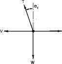
Forward Flight Rate of Climb. Consider a helicopter in a steady climbing altitude compared with the same helicopter in steady level flight, as illustrated in Fig. 5-34.
 |
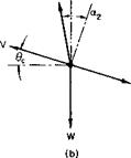 |
Fig. 5-34. Comparison between level and climbing flight: (a) level flight; (b) steady climb.
It was shown earlier that the power required by a rotor can be written approximately as
P = P,+ Pp+ TaV.
Thus the difference in the power required between the steady climb condition of Fig. 5-34 and the level flight condition would be
P = P2-P,= (T2cc2 – T&JV.
Assuming that all angles are small, we determine that
~ W ~ T2 ;
therefore
AP = T(a2 – ocJV.
Equilibrium of forces in the direction of flight for the climbing attitude requires that
Ta2 = D + WO,
or
Wdc = Ta2 – D,
but from the level flight condition D = Tab so that
W6C – T(ol2 — a,).
If both sides are multiplied by V, it follows that W6CV = T(a2 – a,)F
or
WVC = A P,
where Vc = rate of climb = V0C.
АР = difference in power required between climb and level flight.
For the maximum rate of climb at any V, AP should be a maximum, which means that AP should equal Pxs, the excess power, or the power available in excess of that required for level flight. Thus the maximum rate of climb in forward flight at a particular speed is
r. – (5-5»)
This equation does not apply in vertical flight, for the power required to hover cannot be compared with that required for vertical flight. It also does not apply for relatively low forward speeds for which the small angle assumptions are no longer valid.
Equation (5-59) can also be derived from energy considerations, for WVC is the rate of increase in the potential energy of the helicopter which can be
|
Fig. 5-35. Climb performance. |
supplied by the excess power available over that required for level flight. From (5-59) Ve obviously has its maximum value at the forward velocity that corresponds to the minimum power required for level flight.
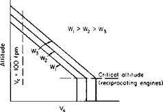
The climb performance in forward flight can now be determined by evaluating (5-59) at different gross-weight and altitude combinations. The variation of rate of climb for different gross weights appears qualitatively in Fig. 5-35.
Absolute Ceiling. The absolute ceiling for the helicopter is the altitude for a given gross weight at which the rate of climb is equal to zero. The variation of absolute ceiling with gross weight can be determined by cross-plotting the values of altitude versus W for Vc = 0.
Service Ceiling. By definition, the service ceiling is the altitude for a given gross weight at which the rate of climb is equal to 100 fpm. Again, it can be determined as a function of gross weight by cross-plotting the altitude versus W for Vc = 100 fpm.
Time-to-Climb. The time-to-climb to any altitude can be readily determined once the rate of climb as a function of altitude is known. The altitude, time-to-climb, and rate of climb are related by the integral equation:
![]() (5-60)
(5-60)
If Vc can be related to the altitude by a linear equation
К = Ко – Kch,
|
= Ao, Ко К ‘~oe V — Kh V °ge V ’ ■*VC *CO rCQ rc |
then Eq. (3-8) can be written as
where h0 is the absolute ceiling.
Observe that the time-to-climb to absolute ceiling is infinite.
Hover Ceiling. The hover ceiling, in- and out-of-ground effect, is readily determined from the CT — CP curves and the ground effect curve, as given in Figs. 5-4 and 5-5, respectively. At each altitude, beginning with the power available, the power coefficient Cp can be calculated from
550BHP
C„ = —— 5—
p pAVP
Knowing the tip speed VT and the speed of sound at altitude, we can calculate the tip Mach number. Then, from the CT versus Cp curve, the value of CT can be determined. The value of the rotor thrust is found from
T = pAV2TCT.
Finally, the gross weight that can be hovered at the power available is found by correcting the thrust for download according to Eq. (5-13) and for overlap according to Fig. 5-7. This would be the maximum gross weight that would be hovered out-of-ground effect at the particular altitude under consideration.
The same procedure is followed for calculating the hovering weight IGE, with the exception that the power available is increased by the reciprocal of the factor given in Fig. 5-5. The end effect on the gross weight will be nearly the same as if the gross weight to hover OGE were multiplied by the reciprocal of the factor in Fig. 5-5. This results from the fact that, within limits, the ratio of the increase in hovering gross weight to an increase in the power available is nearly constant.
The technique of linearizing the effect of design changes about a normal configuration can prove very useful, provided the aerodynamicist realizes the limitations. For example, after the geometry of a helicopter is established,
it can be advantageous to determine for the design conditions such quantities as the following:
1. Pounds of hovering weight per horsepower.
2. Horsepower per square foot of flat plate area.
3. Miles of range per square foot of flat plate area.
4. Equivalent pounds of gross weight per square foot of flat plate area.
 |
From these the approximate effects of minor design changes on the performance can be quickly estimated.
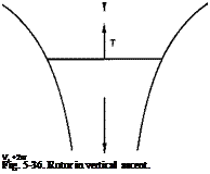
Vertical Ascent. A rotor in vertical ascent is shown in Fig. 5-36. According to momentum theory, the power required to produce the thrust T is given by
For a hovering rotor this becomes
If it is assumed that the profile power of the blades remains unchanged in vertical ascent, then, for the same thrust, the difference in the power required between the vertical ascent and hover is
In terms of Pio this becomes
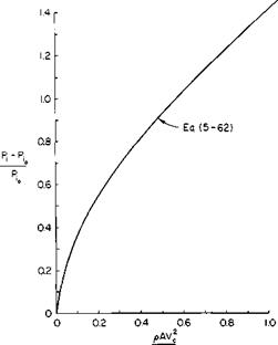
![]() P, – Pi0 1 + (1 + 2T/pAV2)112 Pi0 (2 T/pAV^2
P, – Pi0 1 + (1 + 2T/pAV2)112 Pi0 (2 T/pAV^2
This equation is plotted in Fig. 5-37. To find the velocity Vc for a given gross weight and power available, the power required to hover is determined from Fig. 5-4. The quantity P, — Pio will then be the power available minus the power required to hover. Pio can also be determined from Fig. 5-4 or estimated by increasing Eq. (5-1) 10 to 15%. The ratio of P, — Pio to Pio can now be found and the quantity 2T/AV^p found from Fig. 5-37.
The Hingeless Rotor. Interest has recently been revived in the cantilevered blade without articulation, as described, for example, in Ref. 18. Modern
|
2T Fig. 5-37. Determination of vertical rate of climb. |
advances in blade materials and careful design analyses makes such a blade, frequently referred to as the “rigid rotor” because of the absence of flapping hinges, appear promising. This term is really a misnomer, however, because the blade is flexible and does in a sense flap in response to the airloads.
With the exception of the flapping relationship, the material that has been presented generally applies as well to the hingeless rotor. However, somewhat analogous to hinge-offset, a moment can be imposed on the fuselage by the rotor. This appears to be one advantage of this type of rotor, namely, that its response to control movements is more rapid because of the moment transfer.
According to the reference, the cyclic stresses for the hingeless rotor are well below the allowable fatigue life of available materials. However, proponents of the articulated rotor argue that in this regard the hingeless rotor is marginal. Undoubtedly more effort is needed in this area, but it is also as certain that the hingeless rotor has been developed to a workable state and offers a definite alternative to the articulated rotor. Its proponents offer as its advantages improved stability, high maneuverability, increased allowable CG travel, and simplicity in the hub design.
Problems
1. Given a small single-place helicopter with a gross weight of 1000 lb, determine how much power is required to hover at standard sea level conditions for a disk loading of 6 psf and a tip speed of 700 fps. Use the graph of Fig. 5-4. The helicopter has an equivalent vertical flat plate area of 30 ft2.
2. At what frequency would a weight being whirled around on a string at an rpm of N oscillate if perturbed from its plane of motion?
3. A rotor has 7° of washout, a solidity of 0.07, and incorporates a 0012 airfoil. Each of its three blades weighs 1 lb/ft. It has a diameter of 30 ft and tip speed of 650 fps. What cyclic pitch is required to keep the tip path plane horizontal at a forward speed of 100 mph?
4. Construct a CT versus Cp curve for M = 0 for a rotor with a solidity of
0. 08 by correcting Fig. 5-4 for solidity.
5. The helicopter of Problem 1 has an equivalent flat plate area of 2 ft2. The CG is 5 ft below and 2 in. ahead of the rotor shaft. Calculate the power required in forward flight up to a speed at which compressibility and blade stall become significant.
6. Repeat Problem 5 with a wing attached to the helicopter. The wing has an area of 75 ft2 and an aspect ratio of 6. Repeat for different wing-lift coefficients. Assume reasonable profile drag coefficients for the wing.


