Lateral Modes of a Jet Transport
We use the same airplane and flight condition as for the longitudinal modes in Sec.
6.2, and calculate the lateral modes. The nondimensional and dimensional derivatives are given in Tables 6.6 and 6.7. Using these, the system matrix of (4.9,19) is found to be (note that the state vector is [v p г фт.):
|
-0.0558 |
0 |
-774 |
32.2 |
|
-0.003865 |
-0.4342 |
0.4136 |
0 |
|
0.001086 |
-0.006112 |
-0.1458 |
0 |
|
0 |
1 |
0 |
0 |
This yields the characteristic equation
A4 + 0.6358Л3 + 0.9388Л2 + 0.5114Л + 0.003682 = 0 (6.7,2)
The stability criteria are
E = 0.003682 > 0 R = 0.04223 > 0
 |
so there are no unstable modes.
|
Table 6.7 Dimensional Derivatives—B747 Airplane
|
EIGENVALUES
The roots of (6.7,2) are
Mode 1 (Spiral mode): A, = -0.0072973
Mode 2 (Rolling convergence): A2 = -0.56248
Mode 3 (Lateral oscillation or Dutch Roll): A3 4 = —0.033011 ± 0.94655/
Table 6.8 shows the characteristic times of these modes. We see that two of them are convergences, one very rapid, one very slow, and that one is a lightly damped oscillation with a period similar to that of the longitudinal short-period mode.
EIGENVECTORS
The eigenvectors corresponding to the above eigenvalues are given in Table 6.9. In addition to the basic 4 state variables, Table 6.9 contains two extra rows that show the values of the two state variables ф and yE (see Exercise 6.2).
MODE 1: THE SPIRAL MODE
From Table 6.9, we find the ratios of the angle variables in the spiral mode to be
р:ф:ф= -0.00119:—0.177:1
so that the motion is seen to consist mainly of yawing at nearly zero sideslip with some rolling. This is, of course, the condition for a truly banked turn, and this mode
|
Table 6.8 Characteristic Times—Lateral Modes
|
|
Table 6.9 Eigenvectors (polar form)
|
can be thought of as a variable-radius turn. The aerodynamically important variables are
/3 :p:r = 1:—0.137:0.773
and the largest of these, /3, has already been seen to be negligibly small for moderate values of ф and ф. The aerodynamic forces in this mode are therefore very small, and it may be termed a “weak” mode. This is consistent with its long time constant.
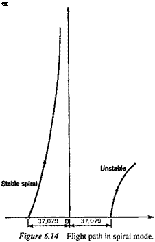
The flight path in the spiral mode can readily be constructed for any given initial yaw angle from the eigenvector. For example, with an initial ф of 20° (0.35 rad), we have from Table 6.9
ф = 0.35eAl’
v = 774(—0.00119)0.35eAl’ fps where A, = -0.0072973 s"1
From (4.9,19) and the above it follows that (for в0 = 0)
yE = —37079e-00072973′ ft xE = 774 t ft
Figure 6.14 shows the path—it is seen to be a long, smooth return to the reference flight path, corresponding to yE = 0. When the spiral mode is unstable as is frequently the case, ф, ф, and yE are all of the same sign, and of course all increase with time instead of decreasing, as shown in the figure.
MODE 2: THE ROLLING CONVERGENCE
The ratios of the angle variables in this mode are, from Table 6.9,
/З :ф:ф= -0.0198:1:-0.0562
The mode is evidently one of almost pure rotation around the x axis, and hence its name. The variables that are significant for aerodynamic forces are (/3, p, r) and they are in the ratios
/3 :p:r = 0.278:1:—0.0561
 |
so that the largest rolling moment in this mode of motion is Clpp, and the r contributions are negligible by comparison.
MODE 3: THE LATERAL OSCILLATION (DUTCH ROLL)
 |
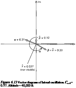
The vector diagram for this mode is shown in Fig. 6.15. It is seen that the three angle variables /3, ф, ф are of the same order of magnitude, that r is an order smaller, and
that /3 and ф are almost equal and opposite. It follows from (4.9,19) that yE is nearly zero. In dimensional terms, when ф = 20°, yF = 8 ft, whereas the wavelength of the oscillation is about 5000 ft. The vehicle mass center is seen to follow a nearly rectilinear path in this mode, the motion consisting mainly of yawing and rolling, the latter lagging the former by about 160° in phase.


