Longitudinal Characteristics of a STOL Airplane
The curves of Fig. 6.5 show that the characteristic modes of an airplane vary with speed, that is with the equilibrium weight coefficient CWo. In particular, the two characteristic periods begin to approach one another as CWg becomes large. It is of interest to explore this range more fully by considering a STOL airplane, operating in the “powered-lift” region for which CWo may be much larger. To this end the data given in Margason et al., (1966) has been used to obtain a representative set of coefficients for 2.0 < CWo < 5.0. The flight condition assumed is horizontal steady flight, so that Cxo = 0. (The particular data used for the reference was that for the aircraft with a large tail in the high position, i, = 0, and Sf = 45°.) From the given curves, and from cross-plots of the coefficients CL, CD, and Cm vs. CT at constant a, the data in Table
6.5 were derived for the equilibrium condition. Smooth curves were used for interpolation. Since this is not a tilt-wing airplane, aT is not large in the cases considered, and has been assumed to be zero.
Since aeroelastic and compressibility effects are negligible at the low speeds of STOL flight the required speed derivatives are given by (see Table 5.1)
For a propeller-driven airplane, the value of CTu is given by (5.3,6), and an examination of the data for a typical constant-speed propeller at low speed[17] showed that dT/du is very small. Hence we have used CTu = —2CTo in this example.
|
cw„ |
CTa |
c^t |
hj |
dCL dCT |
3CD dCT |
dCm dCy |
|
|
2.0 |
0.53 |
5.75 |
1.19 |
0.500 |
0.705 |
0.285 |
-0.090 |
|
2.5 |
0.72 |
6.20 |
1.80 |
0.475 |
0.790 |
0.328 |
-0.070 |
|
3.0 |
0.90 |
6.65 |
2.41 |
0.450 |
0.875 |
0.370 |
-0.050 |
|
3.5 |
1.09 |
7.10 |
3.02 |
0.424 |
0.955 |
0.411 |
-0.030 |
|
4.0 |
1.28 |
7.55 |
3.63 |
0.398 |
1.025 |
0.450 |
-0.010 |
|
4.5 |
1.46 |
8.00 |
4.24 |
0.371 |
1.097 |
0.488 |
+0.010 |
|
5.0 |
1.65 |
8.45 |
4.85 |
0.346 |
1.165 |
0.525 |
+0.030 |
|
Table 6.5 Basic Data for STOL Airplane |
Using the formulae of Table 5.1, the following estimates were made of the q and 6t derivatives:
C = -14, Cm? = -17.9, CZa = -5.5, Cmi = -13
Finally the following inertial and geometric characteristics were assumed:
W = 40,000 lb (177,920 N), S = 1000 ft2 (92.9 m2),
A = 5.42, c = 13.60 ft (4.145m),
H = 76.8, ly = 385, h = 0.30
 |
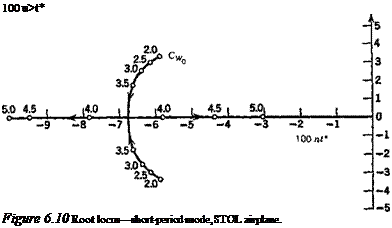
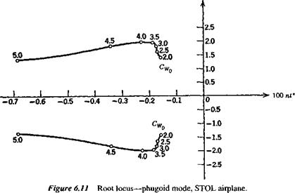
With the above data, the coefficients of the system matrix were evaluated, and its eigenvalues and eigenvectors calculated. The main results are shown on Figs. 6.10-6.13. Figures 6.10 and 6.11 show the loci of the roots as CWo varies between 2 and 5. The effect of CWo is seen to be large on both modes, the short-period mode becoming nonoscillatory at a value of CWa somewhat greater than 3.5, and the damping
|
100 wf
|
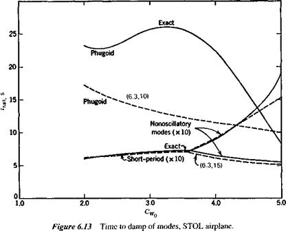
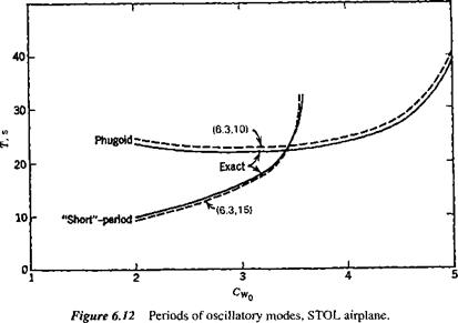
of the phugoid increasing rapidly at the same time. Figure 6.12 shows the two periods, and that they actually cross over at CWo — 3.4. The concept of the phugoid as a “long” period oscillation is evidently not applicable in this situation! The approximations to the phugoid and the pitching mode are also shown for comparison. It is seen that they give the two periods quite well, and that (6.3,15) also depicts quite accurately the damping of the pitching oscillation and of the two nonperiodic modes into which it degenerates at high CWa. The phugoid damping, however, is not at all well predicted by the approximate solution. Figure 6.13 shows that the modes are all heavily damped over the whole range of CWo.
|
|


