Solution of the Flow Over the Unsteady Slender Wing
Solution of the vortex distribution for any given time t, at each x = const, station, is reduced now to solving this equation (Eq. (13.82)) for
y(_y) = y(yt t). Because of the similarity between this case and the steady-state slender-wing case we know that the spanwise circulation (load) distribution is elliptic, as in Eq. (8.74),
Г(у) = Гтах[і – ] (13.83)
and again Г(у) = Г(у, t). The spanwise vorticity distribution (shown in Fig.
8.18)
 |
|
is obtained by differentiating with respect to у (as in Eq. (8.41) or (8.75)):
Substituting this into the integral equation, Eq. (13.82), results in
But this integral has already been evaluated in Chapter 8 (see Eq. (8.77)) and resulted in a constant: —лЬ(х)/2. Substituting this result into Eq. (13.85) yields
1 4Гтах Г-л;Ь(дО] _пдт] ■ dy
2л b(x)2 L 2 J Эх X dt
and after rearranging the terms:
(13.86)
which shows that the spanwise induced downwash due to an elliptic lift distribution is constant and independent of y. The value of Tmax (at each x station and time t) is easily evaluated now and is
Гmax=-b(x)W(x, t) (13.87)
Recalling that the velocity potential can be defined by a path of integration along the local у axis (for an x = const, section),
where the integration starts at the left leading edge of the x = const, station and the integration path is above (0+) or under (0—) the wing.
By substituting y(y) and Гтах into Eqs. (13.79)-(13.81), the crossflow
potential and its derivatives are obtained:
(13.88)
“(*> 3;, 0±, t) = ~(x, y, 0±, t) = |w(jc, ‘)д/[^г] (13.89)
This differentiation can be executed only if the wing planform shape b(x) and chordwise downwash W(x, t) are known. The other derivatives of the velocity potential are
and based on Eq. (13.77), the downwash on the wing is
Once the velocity field is obtained the pressure distribution on the wing can be calculated by using the Bernoulli equation. If the reduced frequencies and the accelerations in the z direction are small, then the pressure is given by Eq. (13.66a):
where the first term is similar to the steady-state (circulatory) term, and the second term is a result of the change of the flow with time. The pressure difference across the thin wing is then
Г ЭФ ЭФ) Э д
Ар =р(х, у, 0-) – р(х, у, 0+) = 2p[t/— + -^-J = pU— АФ + р — ДФ
(13.92)
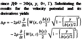 (13.93)
The longitudinal wing loading is obtained by integrating the spanwise pressure
difference and by recalling the result of Eq. (8.88) that
 (13.95)
This is the unsteady version of the slender wing lift (see Section 8.2.3) and a similar formulation was derived by Lighthill13 6 when studying the swimming of slender fish in small-amplitude motion.
In regard to the momentary drag force, recall that the x axis of the coordinate system used for this problem remains parallel to the flight path (Fig. 13.21) and the normal component of the force was designated as lift. Similarly it is possible to define the axial component of the force as drag. Since at each moment for a given set of boundary conditions the potential flow problem is independent of time (excluding the wake influence—which is neglected in this example) the drag component due to the circulatory part of the force can be approximated by the steady-state results of Eq. (8.95). Consequently, owing to the leading-edge suction, the drag due to the circulatory lift (the first term of Eq. (13.95)) is half of the projected pressure difference component:
![]() npU Э
npU Э
2~~4~~dx
while the drag due to the fluid acceleration (second term in Eq. (13.95)) is not reduced by the leading-edge suction. Thus, the instantaneous drag force becomes
Example 1. Heaving oscillations of a slender delta wing. As one of the simplest examples let us consider the small-amplitude heaving oscillations of a slender delta wing. The x, z coordinate system is selected such that it moves to the left of the page at a constant velocity U(t) = t/„. The wing remains parallel to the jt axis, but oscillates up and down at a frequency to and amplitude h0 (see Fig. 13.22). The small displacement of the wing relative to the x axis is then
i](x, t) = h0 sin Ш
FIGURE 13.22
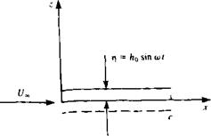 Heaving oscillations of a wing with an amplitude of hn.
Then with v, ei = (0,0, dr}/dt) the time-dependent downwash W(x, t) of Eq. (13.55) becomes
IV(де, f) = — = h0w cos tot at
The longitudinal loading dL/dx is obtained from Eq. (13.95):
— = — л?^°° — 1/|0о)Ь(х)2 cos tot] —[кпшЬ(х)г cos tot] dx 4 dx 4 at
= – —[b(x)2]h0(o cos tot^bixfh^2 sin cot
For a flat triangular delta wing with a chord c and trailing edge span of bT E the span b(x) becomes
x
b(x) — b-r. E. ‘
c
and the longitudinal lift distribution is
dL дгр1У»/>|.Е. , , , лгр(ЬТЕх)2, 2 .
— —————- r – xhnto cos tot + ——— 5-— h0<o sin tot
dx 2 c2 4 c
The lift of the wing is obtained by integrating dLjdx along the chord:
L= [ ~dx = ~~^b2 Eh0(o cos ш + ch0<a2 sin ш (13.97)
Jo dx 4 12
The pitching moment about the apex (де = 0) is
M0 = — f ^X dx = – br. E ch0(o cos cot+ ^§b2T Bc2h0<o2 sin cot (13.98) J0 dx 6 10
As we can see the loads on the wing are created by two terms that have a phase shift between them. The lift of the wing, for example can be divided such that
![]() npU„ 2 xpU„,2 .
npU„ 2 xpU„,2 .
—— b^E. hoW cos tot =———– — by E. T)
 |
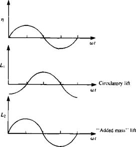 |
The time-dependent vertical displacement of the wing r(i) and these two terms of the lift (Lj, L2) are shown schematically in Fig. 13.23. The first term L, resembles the steady-state (circulatory) term and the lift is a result of the instantaneous effective angle of attack. This lags in phase with the motion such that when the wing moves downward it creates lift L, and vice versa. The second term L2 is a result of the wing vertical acceleration (added mass) and is in phase with the motion.
Example 2. Pitch oscillations of a slender delta wing. Another simple example is the small-amplitude pitching oscillations of a slender delta wing. The origin of the x, z coordinate system is now moving to the left of the page at a constant velocity U(t) = U„. The wing is pitching about the point xcg with a frequency (i) and a small amplitude в0 (shown in Fig. 13.24):
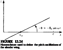 |
в = в0 sin o>t
The wing’s chordline rj(x, t) is given then by
tj(x, /) = — (x – jcC|?) tan 0 ~ —(x – xcg)6 = -(дг – xcg)e0 sin cot
By substituting the derivatives of r into Eq. (13.50) the time-dependent downwash W(x, t) is obtained:
W(x, t) = – f/,0o sin cot – в0со(х – xcg) cos cot
Note that the same result can be obtained from Eq. (13.55) by placing the chordline on the x axis and pitching the x-z plane with 0. The longitudinal loading dL/dx is obtained from Eq. (13.95):
dx 4 dx
For a flat triangular delta wing with a chord c and trailing edge span of bT E. the local span b(x) becomes
and the longitudinal lift distribution is
+ [U~.e<fi>x2 cos cot – в0(о2(х3 – x2xcg) sin to/]
The lift of the wing is obtained by integrating dL/dx along the chord:
 |
The pitching moment about the apex (x = 0) is
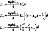
As we can see in this case, too, the loads on the wing can be divided into three terms that have a phase shift between them. The three components can be
rewritten as:
|
and 1-і — Li2 – f – L3. It is clear that the first term is a result of the instantaneous angle of attack while the second term is a result of the downwash caused by the pitch rotation. This part is a function of the pitch axis. The last term is due to the acceleration (added mass) and depends, too, on the location of x^. The damping of the wing due to a constant pitch motion can be found by integrating L2 only in Eq. (13.100): |
ЭМо npU„bn /Зс4 2с3 лрЬтЕ r, c4 npU„L2 ( 2 2c дв ~ 4 7~ T~TXcs)~T~U~4~~ 4 Ьт EC 3 Xcg)
(13.101)


