The Elliptic-Lift Distribution
The spanwise circulation distribution Г(у) for a given planform shape can be obtained by solving Eq. (8.16). In the particular case of an elliptic distribution of the circulation, the solution becomes rather simple since the downwash w, becomes constant along the wing span. Also, as will be shown later, wings having such a spanwise distribution will have minimum induced drag. The proposed distribution of Г(у) is shown in Fig. 8.6 and is
This must be substituted into Eq. (8.16) so that the constant Гтах can be evaluated. For simplicity, let us first calculate the downwash integral (second term in Eq. (8.16)). The term dr(y)/dy is evaluated by differentiating Eq. (8.21):
and the downwash w, is obtained by substituting this result into Eq. (8.10):
Note that when у =y0, this integral is singular and therefore must be evaluated based on Cauchy’s principal value. It is possible to arrive at Glauert’s integral (Eq. (5.22)) by the transformation
|
b У = 2 cos e |
(8.23) |
|
dy = —xsin в d6 2 |
(8.23а) |
|
and at the wing tips у = – b/2, в = ж and at у — b/2, в = (8.21) to |
0. This reduces Eq. |
|
Г(0) = Гтах[1 – cos2 в)1’2 = Гтах sin в |
(8.21а) |
|
г! |
![]()
![]() FIGURE 8.6
FIGURE 8.6
v Elliptic spanwise distribution of the circulation Г(у).
|
св, г лЬ L = pQj Г(у) dy = — pQ*. Г„ •’—6/2 ^ |
|
-2Г -*’1 rr |
![The Elliptic-Lift Distribution Подпись: Another feature of the elliptic distribution is that the spanwise integral is simply half the area of an ellipse (with semi-axes Гтах and b/2) ,6/2 ] г (y)dy = n- J-bf2](/img/3130/image753_3.gif) |
 |
 |
 |
 |
Substituting Eq. (8.23) into Eq. (8.22) yields
![]() 0°(“sin 0O) d6о
0°(“sin 0O) d6о
– (cos в – cos во)
The principal value of this integral can be obtained by using the Glauert integral (Eq. (5.22)):
|
Г 1 max Wi~-2b |
(8.24) |
|
Г A max a‘~2bQa |
(8.24e) |
angle of attack a(y) for the wing with the elliptic circulation distribution. If the chord c(y) has an elliptic form, too, the constant Гтах can be easily evaluated. Thus, assume
where c0 is the root chord. Substituting Eq. (8.31) into Eq. (8.30) cancels the elliptic variation:
For an elliptic planform with constant airfoil shape, all terms but a(y) in this equation are constant, and therefore this wing with an elliptic planform and load distribution is untwisted (a(y) = a = const.). The value of Tmax is then
![]() IbQJ^a – alJ 4 b
IbQJ^a – alJ 4 b
1 +—-
m0c0
 |
|
The area S of the elliptic wing is
Also, it is common to define the wing aspect ratio Ж as
![]() (8.35)
(8.35)
Using the Ж and the area S for the elliptic wing and substituting into Eq.
(8.33)
, Гтах becomes
|
(<x – *L0) = CL'(a – au) |
With this expression for Гтах and using т0 = 2л, the lift coefficient (Eq. (8.28)) becomes
Here CL<x is the three-dimensional wing lift slope and the most important conclusion of this analysis is that this slope becomes less as the wing span becomes smaller due to the induced downwash. This is illustrated by Fig. 8.7, where for a wing with given aL0 the effective angle of attack is reduced by a,
according to Eq. (8.15). Consequently, for finite-span wings, more incidence is needed to achieve the same lift coefficient as the wing span decreases.
The induced drag coefficient is obtained by substituting Eq. (8.35) into
![]() (8.37)
(8.37)
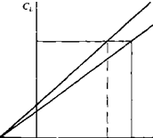
which indicates that as the wing aspect ratio increases the induced drag becomes smaller. Also, the induced drag for the finite elliptic wing will increase with a rate of C as shown in Fig. 8.8.
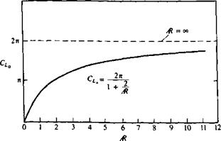
The lift slope CLa versus Ж for the elliptic wing (Eq. (8.36)) is shown in Fig. 8.9. The lift slope of a two-dimensional wing is the largest (2л) and as the wing span becomes smaller CLa decreases too.
The spanwise loading L'(y) (lift per unit span) of the elliptic wing is obtained by using the Kutta-Joukowski theorem:
![]()
 |
||
(8.38)
 |
CL FIGURE 8.8
Lift polar for an elliptic wing.
![]()
|
![]() FIGURE 8.10
FIGURE 8.10
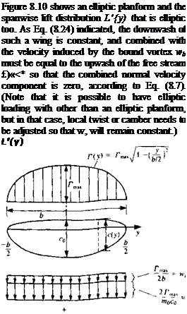
Chord and load distribution for a thin elliptic wing. Note that the induced downwash is constant and combined with the downwash of the bound vortex is equal to the free-stream upwash, resulting in zero velocity normal to the wing surface (Eq. (8.7)).
The section lift coefficient Ct is defined by using the local chord from Eq. (8.31) and is
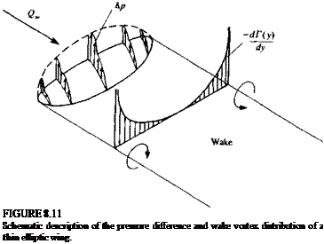
This spanwise wake vortex strength is shown schematically in Fig. 8.11. It is clear from this figure that near the wing tips, where dT(y)/dy is the largest, the wake vortex will be the strongest. Owing to the induced velocity at the wake it will roll up, mostly near the wing tips, to form two concentrated trailing
Flow visualization of the rollup of the trailing vortices behind an airplane (wing tip vortices made visible by ejecting smoke at the wing tips of a Boeing 727 airplane, Courtesy of NASA).

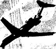 vortices as shown by the flow visualization in Fig. 8.12. The effect of this wake rollup on Г(у) is assumed to be negligible in this model; but this effect can be investigated by the numerical methods of later chapters.


