The Lifting-Line Model
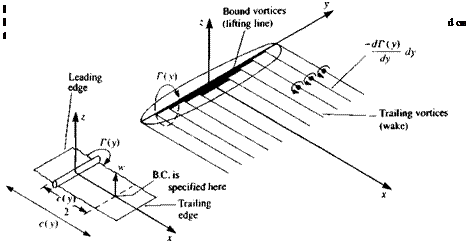
The simplest model that can be suggested to solve this problem is where the chordwise circulation, at any spanwise station, is replaced by a single concentrated vortex. Also, these local vortices of circulation Г(у) will be placed along a single spanwise line. Based on the results of Section 5.5 for the two-dimensional lumped-vortex element, this vortex line will be placed at the wing’s quarter-chord line along the span, – b/2<y <Ы2 (this bound vortex line is assumed to be straight and parallel to the у axis, as shown in Fig. 8.1). The above positioning of the vortex line at the wing’s quarter-chord line effectively satisfies the Kutta condition of Eq. (8.4) as was shown in Section
5.5.
At this point, attention needs to be focused on the vortex theorems requiring that a vortex line cannot start or end abruptly in a fluid (or Eq.
(8.5) ). Therefore, if any change of the vortex line strength yx = dT(y)/dy is introduced, it must be followed by introducing a similar vorticity component in the other direction yy. In other words, the vortex line does not terminate at this point but it changes direction, and its strength remains constant.
The most physical application of these principles is to “shed” these trailing vortices into the flow and create a “wake” such that there will be no force acting on these free vortices Following Section 4.7, this requirement reduces to the condition that the flow along this segment must be parallel to Г (where positive Г is according to the right-hand rule)
q x rwake = 0 (8.6)
The most basic element that will fit these requirements will have the shape of a “horseshoe” vortex (Fig. 8.1), which will have constant “bound vorticity” Г along its quarter-chord line, will turn backward at the wing tips and will continue far behind the wing, and eventually will be closed by the starting vortex. It is assumed here that the flow is steady and therefore the starting vortex segment is far downstream and its influence can be neglected.
A more refined model of the finite wing was first proposed by the German scientist Ludwig Prandtl (see Ref. 5.2) during World War 1 and it uses a large number of such spanwise horseshoe vortices, as illustrated by Fig.
8.2 (the following analysis is in the spirit of this early model). The straight bound vortex T(y) in this case is placed along the у axis and at each spanwise station the leading edge is 1/4 chord ahead of this line and the local trailing edge is 3/4 chord behind the vortex line. Now, let’s examine the integral equation (Eq. (8.3)) for the case of the flat lifting surface, where B-q/Bx =0.
The equation now simply states the boundary condition of Eq. (8.2):
![]()
 |
дФ»іп8 | ЭФ wake ^
dz dz
That is, the sum of the normal velocity components induced by the wing tvb = 3<bwing/dz and wake vortices w, = ЗФwake/ dz, plus the normal velocity component of the free-stream flow Q^a must be zero on the wing’s solid boundary:
wb + w, + Q^a = 0 (8.7)
where w is considered to be positive in the +z direction. The subscripts ( )b and ( ), stand for bound (on wing) and induced (by wake) influences, respectively.
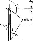
The velocity component wb induced by the lifting line on the section with a chord c(y) can be estimated by using the lumped-vortex model with the downwash calculated at the collocation point which is located at the 3/4 chord. Consider the spanwise component (—y0<y <y0) of a typical horseshoe vortex in Fig. 8.3 with strength ДГ(у0). The downwash Ди^ at the collocation point (c/2, y) due to this segment is given by Eq. (2.69) (see Fig. 2.15, which defines the angles p in this formula) as
-АГ Г У+Уо Уо-У
Алс(у)/2 l_V(c/2)2 + (у +у0)2 /(с/2^ + (уо-у)2
![]()
 |
|
|
|
|
|
|
|
|
|
 |
|
|
|
|
|
|
|
|
|
|
|
![]()
![]()
which is exactly one-half of the velocity induced by an infinite (two – dimensional) vortex of strength АГ(уо)- With the aid of this equation the normal velocity component induced by the trailing vortices of the wing
becomes.
-ДХ-Уо) ,
1 (ba dy dy°
 w‘-t„L —ь – («»>
|
Dividing Eq. (8.11) by the free-stream speed results in ^Г(уо) -Г(у)_____ l_ Ґ* , 4лОО0 L |
 |
(Note that since the trailing vortices are assumed to lie in the 2=0 plane, their induced spanwise velocity component is zero from the Biot-Savart Law, Eq. (2.68b).) Assuming that the wing aspect ratio is large (b/c(y)»1) has allowed us to treat a spanwise station as a two-dimensional section and to transfer the boundary condition to the local three quarter chord. Substituting Eqs. (8.8) and (8.10) into Eq. (8.7) yields
where the induced downwash angle is (note that w is positive in the positive z direction)
![]() (8.13)
(8.13)
Equation (8.12) can be rearranged as
![]() ae = a — or,
ae = a — or,
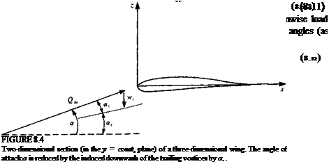
This means that in the case of the finite wing the effective angle of attack of a wing section ae (the angle between the modified free stream velocity q in Fig.
8.4 and the chord) is smaller than the actual geometric angle of attack a by an which is a result of the downwash induced by the wake.
It is possible to generalize the result of this equation by assuming that the two-dimensional section has a local lift slope of m0 and its local effective angle of attack is ae. Now, if camber effects are to be accounted for too, then this angle is measured from the zero-lift angle of the section, such that
с’м-тГЫуМу> <814)
Consequently, Eq. (8.12a) becomes
oce = a – 4- aLo (8.15)
|
<*Г(Уо) dy |
|
+ c*(y)- aLo(y) = 0 |
where is the angle of zero lift due to the section camber (for cambered airfoils, usually au is a negative number). A more general form of Eq. (8.11a) that allows for section camber and wing twist ar(y) is now
In this equation a(y) is the local angle of attack relative to Q« and aLo(y) is the airfoil section zero-lift angle. If it is assumed that these geometrical quantities are known, then Г(у) becomes the unknown in this equation. Also, at the wing tips the pressure difference [or the lift pQS(y = ±6/2)] must reduce to zero:
r(y = ±^) = ° (8-17)


