Transonic airfoils Airfoil performance characterization
For a compressible airfoil flow, both Cd and a depend on the three parameters a, , ReTO. But when examining airfoil performance it’s more useful to combine these into the form,
Cd(ce, M^,Be
CO )
 |
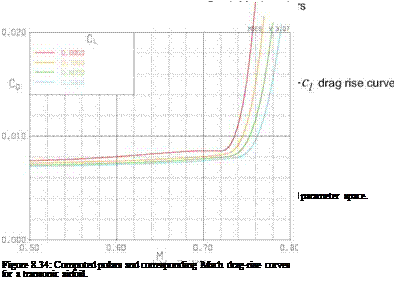
in which a is a dummy parameter. We can now consider individual drag polars at fixed, or alternatively individual Mach drag-rise curves at fixed q. These two types of slices through the |cd, c^,M00j airfoil parameter space are sketched in Figure 8.33. To allow application to a swept wing, the Cd is actually broken down into separate friction and pressure drag components Cdf and Cdp, with the split either estimated or computed directly. Actual computed curves are shown in Figure 8.34.
Strictly speaking all these drag coefficients also depend on ReTO, but with the fully-turbulent flows found on large jet aircraft the drag coefficient scales roughly as Cd ~ log(RsTO)-2, which is a quite weak dependence.
Airfoil performance drivers
The fuel weight required by an aircraft to fly a specified range R is given by the Breguet relation,
where WZF is the zero-fuel (landing) weight, and TSFC is the engine thrust-specific fuel consumption. The particular grouping TSFC/M^2 is chosen because for modern turbofan engines this ratio is nearly independent of MTO (i. e. TSFC varies as МЦ2), so that the remaining factor CD/МЦ2Сь isolates and measures the aircraft’s aerodynamic performance for fuel economy. It is therefore of great interest to find the best airfoil, Cl, Mto, and wing-sweep combination which minimizes this parameter.


