Twisted Elliptic Wing
The spanwise loading of wings can be varied by introducing twist to the wing planform. To illustrate the effects of twist, consider a wing with an elliptic chord distribution. For this purpose let us rearrange Eq. (8.44a) such that
This is the governing equation for the coefficients for the circulation distribution for the general case that is described using lifting-line theory. Section 8.1.4 presents an exact solution for an untwisted elliptic planform wing (elliptic loading) but solutions for other cases must be obtained numerically using techniques that will be described in later sections. It is of interest to study the effect of wing twist on the solution for a particular geometry (geometric twist occurs for a spanwise variation of angle of attack and aerodynamic twist occurs for a spanwise variation of the zero-lift angle).
Filotas81 has found a closed-form solution for a wing with an elliptic planform and arbitrary twist and that solution will be presented in what follows. Consider an elliptic chord distribution as given in Eq. (8.31):
![]() с = c0 sin в
с = c0 sin в
and for simplicity let m0 = 2л. Then Eq. (8.58) becomes
where the aspect ratio of the elliptic wing is Ж = 4b/nc0. Note that the above equation is a Fourier series representation for the right-hand side whose coefficients are given by
To find the wing lift coefficient, the coefficient Ax is obtained as
and the lift is obtained by using Eq. (8.51):
![]()
Example 1. As an example consider a wing with a linear twist where
The effect of the twist can be analyzed by taking the variable part of »(y) only, and adding the contribution of the constant angle of attack later. Therefore, let
ar(y) – a01 cos 0|
and by using Eq. (8.60) the coefficients A„ are computed as
A 4 1 Г*’2 2 1 C*’2
— = — — cos 0 sin 0 sin пв dd —————— ;—— I sin 20 sin n6dd
a0 лЖ/2 + nJo лЖ/2 + nJo
_2 1 Г sin (n – 2)0 sin (n + 2)01л’2
гЖ/2 + nl 2(n — 2) 2(n+2) J0
_ 1 1 Гsin (n — 2)л/2 sin (n + 2)лг/21
лЖ12 + п. (и — 2) (л + 2) J
Evaluating the individual coefficients for a wing with Ж = 6 and for a twist of a = ar0 |cos 0| and substituting into Eq. (8.42) yields
Г(0) = [1 sin 0 + xs sin 30 — sin 50 + ^5 sin 70 + • • •]
л
For a twist of a = ar0(— |cos 0|), the circulation is
Г(0) = 2bQ„a0 sin 0 _ x s;n 30 + ^ sin 50 – їв sin 70 + • ■ ■]
Я
 |
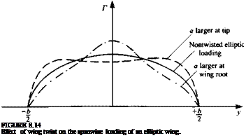
These results, combined with an additional constant angle of attack a are plotted schematically in Fig. 8.14, which shows that having a larger angle of attack at the tip will increase the load there. Similarly, larger angles of attack near the wing root will increase the loading there.
8.1.6 Conclusions from Lifting-Line Theory
The most important result of the lifting-line theory is the ability to establish the effect of wing aspect ratio on the lift slope and induced drag. Some of the more important conclusions are:
1. The wing lift slope dCJda decreases as wing aspect ratio becomes smaller (as shown by Eq. (8.36) for an elliptic wing and by Eq. (8.57) for a wing with general span wise circulation).
2. The induced drag of a wing increases as wing aspect ratio decreases (as shown by Eq. (8.37) for an elliptic wing and by Eq. (8.53) for a wing with general spanwise circulation).
3. A wing with elliptic loading will have the lowest induced drag and the highest lift, as indicated by Eqs. (8.53) and (8.57).
4. This theory also provides valuable information about the wing’s spanwise loading, and about the existence of the trailing vortex wake.
5. The theory is limited to small disturbances and large aspect ratio and, also, Eq. (8.6), which requires that the wake be aligned with the local velocity, was not addressed at all (because of the small angle of attack, a, assumption).
6. There are possible modifications to this theory, such as the addition of wing sweep (e. g., Weissinger82). However, the study of wings with more complex geometry is difficult with this model, whereas some of the more refined methods (introduced in the following chapters) are clearly more capable in dealing with this problem.
7. Using the results of this theory we must remember that the drag of a wing includes the induced drag portion (predicted by this model) plus the viscous drag which must be taken into account.
8.2 SLENDER WING THEORY
In this chapter three-dimensional solutions that rely on the small-disturbance approximation are presented. By assuming that the wing is long and narrow (Ж« 1), and that its angle of attack is small, the special case of slender-wing theory can be developed.
8.2.1 Definition of the Problem
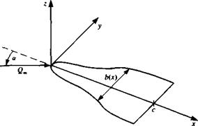
Consider the slender wing of Fig. 8.15 with a span b(x) and root chord c, where both the wing camberline rj and its angle of attack are small:
tan a « 1 and — « 1
c
and we consider wings with no spanwise camber (drf/dy= 0). The flow is
FIGURE 8.15
 Nomenclature for a slender, thin, pointed wing.
assumed to be incompressible and irrotational and therefore the continuity
equation is
V2<t> = 0 (8.62)
with the boundary condition requiring no flow across the wing solid surface. This will be approximated at z = 0 for this case of small angle of attack and the 2 component of the total velocity w*(x, y, 0±) must be zero:
w*(x, y, 0±) = ^ (x, y, 0±) – = 0 (8.63)
In order to solve this problem, singularity elements that create antisymmetry (pressure jump) in the z direction are sought. The doublet solution based on the Э/dz derivative (see Eq. (3.36)) is the most suitable and it is developed for the general lifting surface in Section 4.5. By distributing these doublet elements over the surface of the wing, we obtain the following integral equation (Eq. (4.45)) for the boundary condition of zero normal flow:
J_ [ Фо, у0)[ (x-x0) 1 ,
4л Jwing+wake (y ~ To)2 L V(* – x0)2 + (y – To)2 + Z2 0 0
(8-64)
This integral is singular and its principal value must be evaluated, but before proceeding further, owing to the slender wing assumption some simplifications can be made. Since for the slender wing x»y, z we can assume that the derivatives are inversely affected:
![]() э_ э_ _э
э_ э_ _э
Эх ду ’ dz
Substituting this into the continuity equation (Eq. (8.62)) allows us to consider
the first term as negligible, compared to the other derivatives:
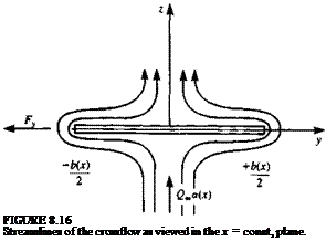
This can be interpreted such that the cross-flow effect is dominant, and for any x station, a local two-dimensional solution is sufficient. This is described schematically in Fig. 8.16. Also, for small-disturbance compressible flow (see Section 4.8), this implies that the Mach number dependency is lost and these solutions are applicable to supersonic potential flows as well.
Since the flowfield is now sought in the two-dimensional plane (jc = const.), the angle of attack and camber effects can be included in a local angle of attack <*(*) such that
, v dt}
|
the kernel in the integral of Eq. (8.64) becomes (*-*o) 1 p |
Recalling the slenderness assumption that
 |
The physical interpretation of this result is that portions of the wing ahead of a given * section (де > дс0) will have influence on the wing, whereas the influence of wing sections and the flow field behind this x section (x < x0) is negligible— thus the effect of the trailing wake for slender wings is small] By substituting this result into the boundary condition (Eq. (8.64)) and recalling that on the
wing z = 0, Eq. (8.64) reduces to
which must be solved for any x = const, wing station with local span b(x). Note that by selecting the doublet distribution in the two-dimensional cross section, this boundary condition can be independently derived by integrating the two-dimensional doublet-induced velocity (Section 3.14).


