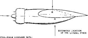
YAW MOMENTS OF FUSELAGES
The longitudinal moments of slender bodies are presented in Chapter XIX dealing with these bodies. The yaw moment characteristics of airplane fuselages are as follows.
Basic Moments. Theoretically (without viscosity, boundary layer, etc.) any elongated body such as a circular cylinder for example, in longitudinal (axial) flow, develops a destabilizing moment. This moment tends to turn the cylinder or any streamline body into the stable position at or near oC ox/S = 90°. Also, under ideal conditions, there is neither drag nor lift. Accordingly, the ideal moment is “free”, it is independent of the point of reference. In reality, every “slender” body develops a type of lift normal or lateral force, similar to that as found in slender wings.
Contrary to conditions in such wings (where the linear lift component is concentrated near the leading edge), this force originates by way of viscous boundary layer momentum losses, primarily in the rear half of the body length. Thus with conventional fuselages the yaw moment resulting from such lateral forces, is stabilizing.
|
REFERENCE POINT SHAPE CY x/f Cna. C STABILITY J/d IFOR Cna . * 9P 4
NOSE POINT – REFERENCE FOR YAH MOMENT Cn. Figure 2. Directional characteristics of a series of streamline bodies or fuselages. Fineness Ratio. A series of three streamline bodies is shown in figure 2, varying in length/diameter ratio between 5 and 10. The yaw moment of these bodies is presented in form of the coefficient |
C^=“N”/qid2 (3)
To facilitate analysis, the moment is also referenced to the nose of the bodies, in form of the derivative
C7?^S = ^7ty5 + °-5 (4)
where 0.5 = A x/jL == distance between the nose point and the original reference axis at 0.5/. Any moment about the nose point is the sum of two components:
1) the destabilizing theroetical or the moment based on ideal flow.
2) the stabilizing moment due to the lateral force.
As explained in Chapter XIX on “slender bodies”, the maximum moment based on ideal flow approximately corresponds to
Cyp = — 0.015 (destabilizing) (5)
In comparison to this equation, the theoretical moment decreases if the fullness of the body shape and/or the length ratio is reduced. The theoretical derivative is approximately:
Су,* = — 0.015 for high length to diameter ratios
= — 0.012 for length = 6 (diameter)
= — 0.009 for length = 4 (diameter)
Lateral Force. As noted in figure 2 the lateral force coefficient of the bodies is referred to the squard of their diameter
Cy4 =Y/qd2 (6)
the derivative of this coefficient increases approximately in proportion to the length ratio. This means that the lateral force grows in proportion to wetted area, skin friction and drag. If referring the coefficient to the “area” (di ) the roughly constant force derivative
dCy I dp = (d/i ) dCyd I dp = 0.003 (7)
is obtained. This value must be expected to vary in proportion to the body’s drag coefficient (shape, surface roughness, appendages, interference).
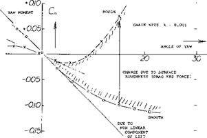
Roughness. The streamline body in figure 3, was tested (2j) in smooth condition as well as with stand-type roughness applied to the surface. Using a grain size к of 0.9 mm, so that кЦ ^ 0.001, the minimum drag coefficient was increased fourfold and the lateral force was doubled. In non-viscous fluid flow, the longitudinal of yaw moment would correspond to equation 5. Considering skin friction and when adding roughness, two things are to be expected:
1) the theoretical destabilizing moment will be reduced
2) part of that moment will be replaced by lateral force.
![]() Since the force is likely to develop or to be centered in the rear half of the body length, the corresponding moment about the fuselage’s or airplane’s CG, is usually stabilizing.
Since the force is likely to develop or to be centered in the rear half of the body length, the corresponding moment about the fuselage’s or airplane’s CG, is usually stabilizing.
|
|||
|
|
||
|
|||
|
|||
|
|||
|
|||
|
![]()
![]()

![]()

|
at = ZERO
|
Figure 3. Directional characteristics of a simple fuselage body, tested (2,j):
a) in smooth condition,
b) with sand-type roughness added.
(2) Directional characteristics of fuselage bodies:
a) See references in the chapter on “slender bodies”.
b) Allen, Influence of Viscosity, NACA Rpt 1048 (1951).
c) Queijo, Tail Size and Length, NACA Rpt 1049 (1951).
d) Lichtenstein, Tail Length, NACA Rpt 1096 (1952).
e) Bates, Flat Fuselage Shapes, NACA TN 3429 (1955).
f) Letko, Cross Section Shape, NACA TN 3551 (1955).
h) Letko, Cross-Section Shapes, NACA TN 3857 (1956).
i) Pass, Directional Stability Information, NACA TN 775 (1940).
j) Engelhardt & Hoerner, Influence of Surface Roughness, Rpt Aerodynamic Laboratory TH Munich 1/1943.
![]()

![]()
![]()
 Location of Force. In the sand-covered body in figure 3, the experimental results can be obtained analytically when reducing the ideal moment equation 5 by 20%, and assuming that the lateral force be centered around 0.6 of the body length. The three lengths in figure 2 have been evaluated, using tested values and equation 5 with a constant of — 0.012 as well as — 0.011. Using equation 7 the stabilizing component due to lateral force, is estimated to be
CnA = + (x/i) 0.003 ЦЦ) (8)
It then seems that the center of the viscous force is at x between 0.6 and 0.8 of the body length.
Shape. It is evident in figure 2, that the body with the round and full forebody has a larger destabilizing moment. On the other hand, the last shape, with a heavier afterbody (and a blunt base) is seen to be more stable. The family of plain fuselage bodies shown in figure 4 was tested (2,f, gji) with the same length and volume, but differing in cross-sectional shape. At angles of yaw up to 8° for one shape and to 15 for another the lateral forces and yaw moments vary in linear proportion to the lateral angle, so that the corresponding derivatives are constant. In terms of fuselage lenth f and the diameter d of the “round” type, results are presented in form of the coefficients defined above. The moment derivative is listed as tested (about the half-length axis) as well as about the nose point. In terms of lateral force the rectangular shapes behave in a manner similar to “wings”. The “flat” body produces the smallest, and the upright rectangular shape the largest lateral force.
|
0.58 POINT WHERE LATERAL. ^FORCE IS CENTERED
|
|
x ——– ► .46 DITTO FOR 0.01-2 IN E(7)
|
|
((0.53(0.015) = 0.008; 0.010 – 0.008 = 0.002; 0.01И09)2 = 0.009; 0.009 – 0.002 = 0.007; 0.007/0.015 = 0.46 r x/f ) ) .33 CY<* =
AC EQUATION (7) WITH 0.011 0.011 |
– 0.007
ORIGINAL POINT OF REFERENCE 0.33Jf
Figure 4. Lateral and directional characteristics of a family of four basic fuselage shapes, analyzed as explained in the text.
Analysis. All body shapes in figure 4, except the round one, are slightly unstable (about the nose point). This means, considering the fuselages to be wind vanes, they would assume a small angle of yaw (either positive or negative). The lateral curvature of the rectangular shapes evidently produces destabilizing suction forces. Using slender-body theory as presented in Chapter XIX, the basic destabilizing moment corresponds to the derivative as in equation 5 using the maximum height (h) instead of
(d) , and with a constant of 0.011. Referring the moments of all shapes tested, to the diameter (d) of the circular cross section, their theoretical derivatives are
dC^/d = 0.011 (h/d)2 = Cjidp (9)
After subtracting this ideal from the experimental total values, derivatives C77are obtained, tentatively representing the moments due to the tested lateral forces. The center of these forces is then found to be at
XU ~ ^nV/3 (1°)
In the rectangular shapes, the center is between 0.3 and 0.5 of the length. The round shape shows, on the other hand, a location between 0.6 and 0.7 of the length. It seems that the flow goes smoothly around the forward end of this fuselage, and a lateral force only develops on the leeward side of the rear half of the length.
“Ducts”. Figure 5 presents the directional characteristics of a fuselage to which a pair of ‘’ducts” (solid bodies, without internal flow) were added. When exposed to an angle of yaw, the destabilizing moment is increased due to the ducts located on top and below the fuselage. Roughly, the ideal moment might be expected to grow with the square of the combined height “h”, as indicated by equation 5 used with a constant of 0.012. In reality, the lateral area of the fuselage plus duct combination increases at a lesser rate than h. Also, the lateral force, the derivative of which is plotted in the lower part of the graph, is likely to contribute a stabilizing component to the yaw moment. Assuming, for example, a location of the force’s center, 0.3 X behind the yaw axis, approximately 2/3 of the differential indicated, can be explained. For the rest, it can be argued that the constant of equation 5 must reduce, as lateral forces replace the ideal moment.
Lateral Ducts. The vertical inlets shown in figure 5, were also tested when attached to the sides of the fuselage as wing root ducts. The graph shows that the value of the unstable yaw-moment derivative slowly reduces with a reduction of combined width of fuselage plus the pair of ducts. Important is the fact that the moment does not grow with the volume added to the fuselage. Rather, height and lateral projection are responsible for the magnitude of the destabilizing yaw moment. The reduction as
tested, might be explained by viscosity. It should also be noted that the pitching moments of the “ducts” as shown in figure 5, are presented in Chapter XI.
When applying ducts to the side of the fuselage it is generally desirable to install a boundary layer bleed system or allow the duct area to project above the boundary layer. This is necessary so as to provide the engine with air at high levels of ram efficiency. Also, if the inlet ducts supply a single plenum chamber it is possible to encounter a directional instability. Such an instability was encountered on the original F-80 airplane. In this case the airplane tended to yaw to an angle where one side duct had clean air without boundary layer flow, the opposite side being effectively stalled. The stabilizing yaw moment corrected the yaw angle causing the other duct to operate in clean air. This alternate filling of the opposite duct resulted in a yaw oscillation that was unsatisfactory. The addition of boundary layer bleed ducts in the system corrected the problem.
|
HEIGHT RATIO |
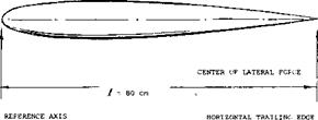
Fuselage Forward. Directional characteristics of a wing – body combinations are presented in figure 6. The “fuselage” in the center might be found in a configuration where the tad surfaces are supported by a pair of booms within a tailless airplane. Dividing the fuselage contributions (based upon wing dimensions):
AC^s/ACyp =-0.0012/0.0010 = – 1.2 = Ax/b
(П)
we find that the neutral point in regard to the moment about the vertical axis, is located at (1.2 b) forward of the CG of the airplane. The yaw moment caused by viscosity and lateral force evidently combines with the ideal moment to make the configuration very unstable. Assuming that this ideal moment may correspond to
C7*3=C//bXdz/S) 0.013 =
0.99 (0.077) 0.013 = -0.0010 (12)
the remaining component is —(0.0012 —0.0010) = —0.0002. Dividing by the derivative of the lateral force coefficient лСУ/з = 0.0010, yields A x/b —0.0002/0.0010 = 0.20. In other words, the center of the lateral force is estimated to be (0.20 b) ahead of the CG at x/j( = 0.55, as shown in the illustration.
|
|
 |
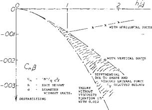
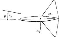
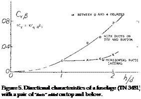
Figure 6. The yaw moment contribution of a forward located fuselage.
Engine Nacelles. The “fuselage” in figure 6 resembles a plain and smooth engine nacelle. Analysis as above, suggests that the stabilizing yaw moment due to lateral force about the CG of a conventional airplane configuration may be small. Equation 7 might thus be adequate to predict the yaw moment due to ordinary engine nacelles. Engine nacelles, installed in the wing, also differ from fuselages as to their length. The ratio X /d is smaller and the nacelle body generally blends into the wing. A model – tested example of a typical nacelle is presented in figure 7.
|
YAW AXIS THROUGH CG
FOCKE-WULF FW-200 LONG RANGE (ATLANTIC) OPERATIONAL ABOUT 1940 |
b = 33 m ENGINE NACELLE TESTED M) ONE OF 4,
S 121 ш2 ON A 1 TO 25 SCALE MODEIL AT
Vx = 360 km/h Rc = 4(10)[116] FULL-SCALE: NACELLE
4 x 720 HP DIAMETER = 1.4 m
CD = 0.02 min
ENGINE NACELLE TESTED AS ONE OF 4,
ON A 1 TO 25 SCALE MODEL AT Rc = 4(10)6 FULL-SCALE NACELLE DIAMETER = 1.4 m
Figure 7. Directional characteristics of an engine nacelle (3,b) tested as part of the wind tunnel model of a 4-engj. ne military airplane.
Splitting the body into two halves, the upper one may roughly have an effective length ratio J( /d = 2, and the lower one = 4. As explained above, the yaw moment coefficient, equation 5, reduces with the length ratio. The reduction factor is about 0.6 for J /d = 4 and 0.4 for X /d = 2; the average is 0.5. Since the length is different in the two halves of the nacelle considered, we will refer the moment as tested to (d3); thus:
C^3 = “N”/qd3 = C^(//d) (13)
Using the factor as above and the average “exposed” length ratio = 3, we obtain from equation 7:
(С7*У% = ~ °-5 (°-013) [117] [118] [119] = – 0.020
This result is slightly higher than the tested value (0.019). Using the experimental lateral force differential due to the nacelle, (Суd )уз = 0.005, a stabilizing component
(Cnd3)A =(Cyd)fi (Ax/d) = 0.005 (Дх/d)
can be found. To explain the difference as above (0.020 — 0.019) = 0.001, the center of Cyd must be assumed to be (0.001/0.Q05) = 0.2 nacelle diameters aft of the yaw axis through the CG (as indicated in the illustration). However, the cowling (ring) at the front end of the nacelle would increase the destabilizing moment above the value of — 0.020 as computed above.
Airplane Configurations. The fuselage and engine nacelles of typical airplane configurations without a vertical tail attached and propellers have destabilizing yaw moments about as follows:
single engine in fuselage C^ =-0.0001 typical twin-engine = — 0.0002
four-nacelle configuration = — 0.0003
These moments are small by comparison with typical vertical tail surface which contributes a stabilizing derivative between 0.0005 and 0.0010.
III. VERTICAL TAIL CHARACTERISTICS
The purpose of die vertical tad surface is to provide directional stability and control moments. Analysis of the yaw moments developed is complicated by the structural connection between tail, fuselage and horizontal surface.


