Comparison of Aeroacoustic Methods
There are no measurements for the oblique BVI case of the model problem previously discussed, but results have been computed using two different aeroacoustic methods; one based on FW-H/linear unsteady aerodynamics approach and the other based on CFD – see Strawn (1997). The latter method consists of a CFD solution on and near the rotor blades, followed by an interpolation onto a surface that encloses the rotor. An acoustics integration scheme propagates the acoustic signal to the far-field. This integration scheme is based on a Kirchhoff Ffowcs Williams-Hawkings (KFWH) acoustics formulation. An Euler flow solver (Section 14.2.2) computes the near-blade CFD solution. All nonlinear effects on the acoustic propagation are accurately modeled within the framework of the
Euler equations. The KFWH formulation is used to propagate the acoustics signal to the far field. The KFWH formulation begins with a derivation of the FW-H equation for the radiated noise from a surface with arbitrary motion. The resulting integral equation reduces to the classic FW-H equation when the chosen surface coincides with the surface of the rotor blades. It reproduces the classic Kirchhoff formulation when the KFWH surface is far from the rotor blades. In this particular case, the CFD grid consisted of 135-by-50-by-35 points in the chordwise, spanwise, and normal directions to the blade surface, respectively. The grid had a C-H topology (refer to Fig. 14.1), and extended approximately 1.5 blade radii above, below, and beyond the blade tip in the spanwise direction. A constant time-step of 0.25 degrees of blade azimuthal motion was used. The KFWH surface consisted of a total of 86,400 mesh points distributed over a top, bottom, and side grid. The linear method used 50 spanwise elements along the blade and an azimuthal step of 0.5°.
 |
 |
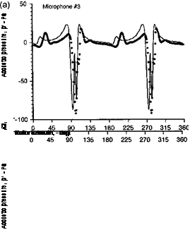
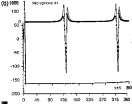
The results are shown Fig. 8.52 for an oblique (y,, = 0.5) case. Results for four reference microphones are shown, three of which lie upstream and below the rotor, with the fourth microphone upstream and in the plane of the rotor. Figure 8.52 shows that the agreement obtained between the FW-H/linear and the CFD/KFWH methods is very good at all of the
![]() Figure 8.52 Comparison of sound pressures using FW-H/linear aerodynamics method and a Kirchhoff/CFD method for an oblique (y,. = 0.5) ВVI case, (a) Microphone 1. (b) Microphone 2. (c) Microphone 3. (d) Microphone 4. See Fig. 8.49 for microphone locations. Vortex at z/c = —0.25, tip Mach number = 0.76, vortex strength Г, = 0.406.
Figure 8.52 Comparison of sound pressures using FW-H/linear aerodynamics method and a Kirchhoff/CFD method for an oblique (y,. = 0.5) ВVI case, (a) Microphone 1. (b) Microphone 2. (c) Microphone 3. (d) Microphone 4. See Fig. 8.49 for microphone locations. Vortex at z/c = —0.25, tip Mach number = 0.76, vortex strength Г, = 0.406.
microphone locations. For the out-of-plane locations, the sound pressure is comprised of contributions from both “loading” and “thickness” sound waves. The in-plane microphone (Microphone 4) receives only the thickness wave, which is exactly the same in both cases (both positive and negative signs of the vortex strength). The agreement between the two computational methods is very good, but the simple source-sink displacement model used in the FW-H/linear method slightly overpredicts the intensity of the thickness sound wave. The out-of-plane microphones receive sound waves from both thickness and loading sources, which results in somewhat more complicated waveforms. In some cases, the sound waves from the various sources arrive just in-phase, and this can result in either constructive or destructive interference depending on the sign (compression or rarefaction) of the BVI wave front. An example of this is shown in Figs. 8.52(b) and (c). This will affect the net directivity in the acoustic field and shows the difficulties in considering just BVI sources alone as contributors to the noise field.
Overall, this type of simple model problem demonstrates the enormous complexity of predicting accurately the noise from an actual helicopter rotor with its plethora of possible BVI locations. However, it seems that if the structure, strength, and location of the tip vortices relative to the blades are known, then aeroacoustic methods have matured to the point where good noise predictions are possible. Of course, on an actual helicopter predicting the spatial and temporal locations of the tip vortices relative to the dynamically flapping and deflecting blades is really the greatest challenge, and one that is still technically beyond the state of the art. This wake problem is considered in detail in Chapter 10. It would seem that until the more thorough and complete integration of more physically representative wake models and tip vortex models into aeroacoustic analyses is completed, the accurate quantitative prediction of rotor noise will always remain an elusive goal.


