Conclusions from Slender Wing Theory
The slender-wing solution presented here is based on the small-disturbance assumption, which automatically restricts the range of wing angle of attack. But in this particular case of slender wings, the incidence range is more limited than for high aspect ratio lifting wings because of flow separation along the leading edges. This effect will be discussed in Chapter 14, and in general, these leading-edge separated flow patterns will begin at angles of attack of 5-10° (depending on leading-edge radius).
The main importance of this slender wing theory is that it provides a three-dimensional solution for the limiting case of very small aspect ratio wings. These results can serve as test cases for more complex panel codes, within the limit of small incidence angles.
The slenderness assumption, where one coordinate is larger than the other two, allowed the local treatment of the two-dimensional crossflow. This logic can be carried over to more advanced methods and also for treating supersonic potential flows. This becomes clear when examining Eq. (4.73), where by omitting the jc-derivatives, the Mach number dependency is lost too.
The wake influence in this analysis was assumed to be small (negligible), which is, again, a good test case for more advanced panel codes.
8.3 SLENDER BODY THEORY
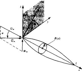
As a final example of classical small-disturbance theories, consider the flow past a slender body of revolution at a small angle of attack a, as shown in Fig.
8.25. It is convenient to use the cylindrical coordinates x, г, в and then the surface of the slender body of revolution is given as
 |
F = r~R(x) = 0 (8.103)
|
*(*) / |
If the length of the body is /, slenderness means that the ratio of body radius R(x) to length is small and for small disturbances, the angle of attack a is small as well:
Laplace’s equation for the perturbation potential (in cylindrical coordinates) is given by Eq. (1.33) as
where r = Vyi + z2.
In this coordinate system the free stream velocity is
Q«, = t/„e, + W»ez = Q»[cos a ex + sin ar(sin в er + cos в e0)]
« Qa°[ex + <*(sin в er + cos в ee)] (8.106)
Following the method of Section 4.2, the zero normal velocity component boundary condition on the body surface is УФ* • VF = 0, which yields
The small-disturbance version of this boundary condition is obtained after neglecting the smaller terms (according to Eq. 8.104):
дФ
— (*, R, в) = Q„R'(x) – Q„a sin в (8.108)
where R'(x) = dR(x)/dx and it is noted that the boundary condition has not been transferred to the body axis. The reason for this is that the velocity components of this flow are singular at the axis and the application of the boundary condition must be performed with care.
At this point it can be seen that the small-disturbance flow past a slender body of revolution at angle of attack can be replaced by two component flows, the axisymmetric flow past the body at zero angle of attack with body boundary condition
^(x, R, d) = Q„R'{x) (8.108a)
dr
and the flow normal to the body axis with free stream speed Qaa and body boundary condition
ЭФ
— (x, R, в) = -QooOr sin в (8.108b)
In the next two sections these two linear subproblems will be formulated and the complete solution is their sum.


